

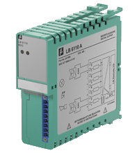
Digital Output LB6111A
- 4-channel
- Outputs Ex ia
- Installation in Zone 2 or safe area
- Line fault detection (LFD)
- Positive or negative logic selectable
- Simulation mode for service operations (forcing)
- Permanently self-monitoring
- Output with watchdog


Please note: All product-related documents, such as certificates, declarations of conformity, etc., which were issued prior to the conversion under the name Pepperl+Fuchs GmbH or Pepperl+Fuchs AG, also apply to Pepperl+Fuchs SE.
Download the complete datasheet as a PDF:
Datasheet excerpt: Technical data of LB6111A
| Slots | ||
|---|---|---|
| Occupied slots | 2 | |
| Supply | ||
| Connection | backplane bus / booster terminals | |
| Rated voltage | 12 V DC , only in connection with the power supplies LB9*** | |
| Power consumption | 0.6 W at power supply 5 W if 24 V booster voltage |
|
| Internal bus | ||
| Connection | backplane bus | |
| Interface | manufacturer-specific bus to standard com unit | |
| Digital output | ||
| Number of channels | 4 | |
| Suitable field devices | ||
| Field device | Solenoid Valve | |
| Field device [2] | audible alarm | |
| Field device [3] | visual alarm | |
| Connection | channel I: 1+, 2-; channel II: 3+, 4-; channel III: 5+, 6-; channel IV: 7+, 8- | |
| Current limit | 60 mA | |
| Internal resistor | 320 Ω | |
| Open loop voltage | 24.5 V | |
| Line fault detection | can be switched on/off for each channel via configuration tool also when turned off (every 2.5 s the valve is turned on for 2 ms) | |
| Short-circuit | < 180 Ω | |
| Open-circuit | > 6 kΩ | |
| Response time | 10 ms (depending on bus cycle time) | |
| Watchdog | within 0.5 s the device goes in safe state, e.g. after loss of communication | |
| Reaction time | 10 s | |
| Indicators/settings | ||
| LED indicator | LED green: supply LED red: line fault , red flashing: communication error |
|
| Directive conformity | ||
| Electromagnetic compatibility | ||
| Directive 2014/30/EU | EN 61326-1 | |
| Conformity | ||
| Electromagnetic compatibility | NE 21 | |
| Degree of protection | IEC 60529 | |
| Ambient conditions | ||
| Ambient temperature | -20 ... 60 °C (-4 ... 140 °F) | |
| Storage temperature | -25 ... 85 °C (-13 ... 185 °F) | |
| Shock resistance | shock type I, shock duration 11 ms, shock amplitude 15 g, number of shocks 18 | |
| Vibration resistance | frequency range 10 ... 150 Hz; transition frequency: 57.56 Hz, amplitude/acceleration ± 0.075 mm/1 g; 10 cycles frequency range 5 ... 100 Hz; transition frequency: 13.2 Hz amplitude/acceleration ± 1 mm/0.7 g; 90 minutes at each resonance |
|
| Damaging gas | designed for operation in environmental conditions acc. to ISA-S71.04-1985, severity level G3 | |
| Mechanical specifications | ||
| Degree of protection | IP20 when mounted on backplane | |
| Connection | removable front connector with screw flange (accessory) wiring connection via spring terminals (0.14 ... 1.5 mm2) or screw terminals (0.08 ... 1.5 mm2) |
|
| Mass | approx. 150 g | |
| Dimensions | 32.5 x 100 x 102 mm (1.28 x 3.9 x 4 inch) | |
| Data for application in connection with hazardous areas | ||
| EU-Type Examination Certificate | PTB 03 ATEX 2042 | |
| Marking |  II (1) G [Ex ia] IIC II (1) D [Ex ia] IIIC II (1) G [Ex ia] IIC II (1) D [Ex ia] IIIC |
|
| Output | ||
| Voltage | 27.8 V | |
| Current | 107 mA | |
| Power | 744 mW | |
| Internal capacitance | 1.65 nF | |
| Internal inductance | 0 mH | |
| Certificate | PF 08 CERT 1234 X | |
| Marking | II 3 G Ex nA IIC T4 Gc |
|
| Galvanic isolation | ||
| Output/power supply, internal bus | safe electrical isolation acc. to EN 60079-11, voltage peak value 375 V | |
| Directive conformity | ||
| Directive 2014/34/EU | EN 60079-0:2009 EN 60079-11:2007 EN 60079-15:2010 EN 61241-11:2006 |
|
| International approvals | ||
| ATEX approval | PF 08 CERT 1234 X PTB 03 ATEX 2042 | |
| IECEx approval | BVS 09.0037X | |
| Approved for | Ex nA [ia Ga] IIC T4 Gc [Ex ia Da] IIIC |
|
| EAC approval | Russia: RU C-IT.MIII06.B.00129 | |
| Marine approval | ||
| Lloyd Register | 15/20021 | |
| DNV GL Marine | TAA0000034 | |
| American Bureau of Shipping | T1450280/UN | |
| Bureau Veritas Marine | 22449/B0 BV | |
Classifications
| System | Classcode |
|---|---|
| ECLASS 13.0 | 27210101 |
| ECLASS 12.0 | 27210101 |
| ECLASS 11.0 | 27210101 |
| ECLASS 10.0.1 | 27210101 |
| ECLASS 9.0 | 27210101 |
| ECLASS 8.0 | 27210101 |
| ECLASS 5.1 | 27210120 |
| ETIM 9.0 | EC001485 |
| ETIM 8.0 | EC001485 |
| ETIM 7.0 | EC001485 |
| ETIM 6.0 | EC001485 |
| ETIM 5.0 | EC001485 |
| UNSPSC 12.1 | 39121008 |
Details: LB6111A
Function
The digital output features 4 independent channels.
The device can be used to drive solenoids, sounders, or LEDs.
Open and short-circuit line faults are detected.
The outputs are galvanically isolated from the bus and the power supply.
Product Documentation: LB6111A
| Product information | Language | File Type | File Size |
|---|---|---|---|
| Selection table - Solenoid driver/valve combinations | ENG | 299 KB | |
| Manuals | |||
| Manual | ENG | 5367 KB | |
Approvals: LB6111A
| Certificates | Certificate No. | Language | File Type | File Size |
|---|---|---|---|---|
| DEKRA EXAM IECEx Certificate of Conformity | IECEx BVS 09.0037X | ALL | LINK | --- |
| DNV Marine | TAA0000034 | ALL | 110 KB | |
| Europe PTB II (2) D II (1D) I (M1) I (M2) II (1) D II (2) G | PTB 03 ATEX 2042X | ALL | 1651 KB | |
| Europe Pepperl+Fuchs ATEX Category 3 G Certificate of Conformity | PF 08 CERT 1234 X | ALL | 1503 KB | |
| United Kingdom CML UK-Type Examination Certificate UKEX Category (1) D UKEX Category (1) G UKEX Category (M1) | CML 21UKEX2663X | ALL | 332 KB | |
| Declaration of Conformity | ||||
| EU Declaration of Conformity (P+F) / EU-Konformitäterklärung (P+F) | DOC-1065F | ALL | 1046 KB | |


The new LB/FB PROFINET gateways from Pepperl+Fuchs open the door for IIoT 4.0 applications in process industries.


Pepperl+Fuchs SE
Lilienthalstraße 200
68307 Mannheim
Germany
info@de.pepperl-fuchs.com
 +49 621 776-0
Pepperl+Fuchs is a leading developer and manufacturer of electronic sensors and components for the global automation market. Continuous innovation, enduring quality, and steady growth have been the foundation of our success for more than 70 years. Pepperl+Fuchs employs 6,300 people worldwide and has manufacturing facilities in Germany, USA, Singapore, Hungary, Indonesia and Vietnam, most of them ISO 9001 certified.