

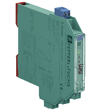
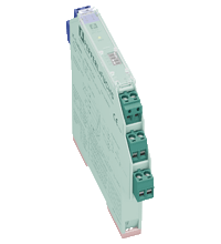
Solenoid Driver KCD2-SLD-Ex1.1245
- 1-channel isolated barrier
- 24 V DC supply (bus or loop powered)
- Output 45 mA at 12 V DC
- Line fault transparency (LFT)
- Test pulse immunity
- Housing width 12.5 mm
- Up to SIL 3 acc. to IEC/EN 61508


Please note: All product-related documents, such as certificates, declarations of conformity, etc., which were issued prior to the conversion under the name Pepperl+Fuchs GmbH or Pepperl+Fuchs AG, also apply to Pepperl+Fuchs SE.
Datasheet excerpt: Technical data of KCD2-SLD-Ex1.1245
| General specifications | ||
|---|---|---|
| Signal type | Digital Output | |
| Functional safety related parameters | ||
| Safety Integrity Level (SIL) | SIL 3 | |
| Systematic capability (SC) | SC 3 | |
| Supply | ||
| Connection | terminals 5+, 6- loop powered Power Rail or terminals 9+, 10- bus powered |
|
| Rated voltage | 19 ... 30 V DC loop powered |
|
| Input current | 75 mA at 24 V , 270 Ω load | |
| Power dissipation | 1.3 W at 24 V , 270 Ω load | |
| Input | ||
| Connection side | control side | |
| Connection | terminals 5+, 6- | |
| Test pulse length | max. 2 ms from DO card | |
| Signal level | loop powered 1-signal: 19 ... 30 V DC 0-signal: 0 ... 5 V DC bus powered 1-signal: 15 ... 30 V DC (current limited to 5 mA) 0-signal: 0 ... 5 V DC |
|
| Rated current | 0-signal: typ. 1.6 mA at 1.5 V DC; typ. 8 mA at 3 V DC (maximum leakage current DO card) 1-signal: ≥ 36 mA (minimum load current DO card) |
|
| Inrush current | < 200 mA , 10 ms loop powered | |
| Output | ||
| Connection side | field side | |
| Connection | terminals 1+, 2- | |
| Internal resistor | 240 Ω | |
| Current | typ. 45 mA | |
| Voltage | typ. 12 V | |
| Current limit | 50 mA | |
| Open loop voltage | typ. 24.6 V | |
| Load | nominal 0.05 ... 18 kΩ | |
| Output II | fault signal | |
| Connection | terminals 7, 8 , non-intrinsically safe | |
| Contact loading | 30 V DC/ 0.5 A resistive load | |
| Mechanical life | 105 switching cycles | |
| Energized/De-energized delay | ≤ 20 ms / ≤ 20 ms | |
| Line fault detection | ||
| Short-circuit | < 25 Ω | |
| Open-circuit | > 50 kΩ | |
| Test current | < 500 µA | |
| Galvanic isolation | ||
| Output/other circuits | basic insulation according to IEC/EN 61010-1, rated insulation voltage 300 Veff | |
| Output II/power supply | basic insulation according to IEC/EN 61010-1, rated insulation voltage 32 Veff | |
| Indicators/settings | ||
| Display elements | LEDs | |
| Control elements | DIP switch | |
| Configuration | via DIP switches | |
| Labeling | space for labeling at the front | |
| Directive conformity | ||
| Electromagnetic compatibility | ||
| Directive 2014/30/EU | EN 61326-1:2013 (industrial locations) | |
| Conformity | ||
| Electromagnetic compatibility | NE 21:2012 , EN 61326-3-2:2008 For further information see system description. |
|
| Degree of protection | IEC 60529:2013 | |
| Protection against electrical shock | EN 61010-1:2010 | |
| Ambient conditions | ||
| Ambient temperature | -20 ... 60 °C (-4 ... 140 °F) Observe the temperature range limited by derating, see section derating. |
|
| Mechanical specifications | ||
| Degree of protection | IP20 | |
| Connection | screw terminals | |
| Mass | approx. 150 g | |
| Dimensions | 12.5 x 119 x 114 mm (0.5 x 4.7 x 4.5 inch) (W x H x D) , housing type A2 | |
| Height | 119 mm | |
| Width | 12.5 mm | |
| Depth | 114 mm | |
| Mounting | on 35 mm DIN mounting rail acc. to EN 60715:2001 | |
| Data for application in connection with hazardous areas | ||
| EU-type examination certificate | EXA 17 ATEX 0002 X | |
| Marking |  II 3(1)G Ex nC ec [ia Ga] IIC T4 Gc II (1)D [Ex ia Da] IIIC I (M1) [Ex ia Ma] I II 3(1)G Ex nC ec [ia Ga] IIC T4 Gc II (1)D [Ex ia Da] IIIC I (M1) [Ex ia Ma] I |
|
| Output I | Ex ia | |
| Voltage | 26 V | |
| Current | 110 mA | |
| Power | 715 mW | |
| Supply | ||
| Maximum safe voltage | 60 V (Attention! The rated voltage can be lower.) | |
| Input | ||
| Maximum safe voltage | 60 V (Attention! The rated voltage can be lower.) | |
| Collective error message | ||
| Maximum safe voltage | 60 V (Attention! The rated voltage can be lower.) | |
| Galvanic isolation | ||
| Output I/other circuits | safe electrical isolation acc. to IEC/EN 60079-11, rated insulation voltage 300 Vrms | |
| Directive conformity | ||
| Directive 2014/34/EU | EN 60079-0:2012+A11:2013 , EN 60079-7:2015 , EN 60079-11:2012 , EN 60079-15:2010 | |
| International approvals | ||
| UL approval | E106378 | |
| Control drawing | 116-0448 (cULus) | |
| IECEx approval | ||
| IECEx certificate | IECEx EXA 17.0001X | |
| IECEx marking | Ex nC ec [ia Ga] IIC T4 Gc [Ex ia Da] IIIC [Ex ia Ma] I |
|
| General information | ||
| Supplementary information | Observe the certificates, declarations of conformity, instruction manuals, and manuals where applicable. For information see www.pepperl-fuchs.com. | |
Classifications
| System | Classcode |
|---|---|
| ECLASS 13.0 | 27210101 |
| ECLASS 12.0 | 27210190 |
| ECLASS 11.0 | 27210190 |
| ECLASS 10.0.1 | 27210190 |
| ECLASS 9.0 | 27210190 |
| ECLASS 8.0 | 27210190 |
| ECLASS 5.1 | 27210121 |
| ETIM 9.0 | EC001485 |
| ETIM 8.0 | EC001485 |
| ETIM 7.0 | EC001485 |
| ETIM 6.0 | EC001485 |
| ETIM 5.0 | EC001485 |
| UNSPSC 12.1 | 39121008 |
Details: KCD2-SLD-Ex1.1245
This isolated barrier is used for intrinsic safety applications.
It supplies power to solenoids, LEDs and audible alarms located in a hazardous area.
The device is controlled with a loop powered signal or a bus powered logic signal.
The device is immune to the test pulses of various control systems.
The device simulates a minimum load at the input. The minimum load can be activated and de-activated.
The line fault transparency function can display a line fault in the field by a change in impedance at the switching input of the solenoid driver.
A line fault is indicated by a red LED and output via the fault indication output or a switch contact.
Datasheet: KCD2-SLD-Ex1.1245
| Datasheet | File Type | File Size |
|---|---|---|
| Datasheet KCD2-SLD-Ex1.1245 | 999 KB | |
| Fiche de données KCD2-SLD-Ex1.1245 | 1006 KB | |
| Datenblatt KCD2-SLD-Ex1.1245 | 1002 KB | |
| Datasheet KCD2-SLD-Ex1.1245 | 1003 KB | |
| Hoja de datos KCD2-SLD-Ex1.1245 | 1009 KB |
Documents: KCD2-SLD-Ex1.1245
CAD+CAE: KCD2-SLD-Ex1.1245
| CAD | File Type | File Size |
|---|---|---|
| CAD 3-D / CAD 3-D | STP | 3088 KB |
| CAD Portal / CAD Portal | LINK | --- |
| EPLAN | ||
| CAE EPLAN Data Portal / CAE EPLAN Data Portal | LINK | --- |
| CAE EPLAN macro EDZ / CAE EPLAN Makro EDZ | EDZ | 1576 KB |
Approvals+Certificates: KCD2-SLD-Ex1.1245
| Certificates | File Type | File Size |
|---|---|---|
| Brasil TUV Rheinland Brazil | 1240 KB | |
| China SITIIAS CCC Ex Certificate | 1300 KB | |
| EXA IECEx Certificate of Conformity | LINK | --- |
| Europe EXA ATEX Category (1) D ATEX ATEX Category (M1) ATEX Category (1) G ATEX Category 3 G | 2278 KB | |
| Japan CML | 276 KB | |
| Korea KOSHA | 691 KB | |
| USA Canada UL Hazardous Location Certificate of Compliance cULus UL E106378 | 414 KB | |
| United Arab Emirates SGS Gulf Limited ECASEx | 603 KB | |
| United Kingdom CML UKEX Category (1) D UKEX Category (M1) UK-Type Examination Certificate UKEX Category 3 (1) G | 308 KB | |
| Control Drawings | ||
| Control drawing UL / Control drawing UL | 89 KB | |
| Declaration of Conformity | ||
| EU Declaration of Conformity (P+F) / EU-Konformitäterklärung (P+F) | 88 KB |
Associated Products: KCD2-SLD-Ex1.1245
| Matching System Components | ||||||
|---|---|---|---|---|---|---|
|
||||||
|
||||||
|
||||||
|
||||||
|
||||||
|
||||||
| Accessories | ||||||
|
||||||
|
||||||
|
||||||


Choose from various selection criteria like safety integrity level, performance level, device function, and signal type and find the SIL/PL assessed device that you are looking for.


Pepperl+Fuchs GB Ltd.
77 Ripponden Road
Oldham OL1 4EL, Lancs.
United Kingdom
sales@gb.pepperl-fuchs.com
 +44 161 6336431
Pepperl+Fuchs is a leading developer and manufacturer of electronic sensors and components for the global automation market. Continuous innovation, enduring quality, and steady growth have been the foundation of our success for more than 70 years. Pepperl+Fuchs employs 6,300 people worldwide and has manufacturing facilities in Germany, USA, Singapore, Hungary, Indonesia and Vietnam, most of them ISO 9001 certified.