

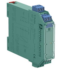
Potentiometer Converter KFD2-PT2-Ex1-5
- 1-channel isolated barrier
- 24 V DC supply (Power Rail)
- Potentiometer input
- Current output 4 mA ... 20 mA
- Lead resistance compensation adjustment
- Accuracy 0.05 %
- Up to SIL 2 acc. to IEC/EN 61508


Please note: All product-related documents, such as certificates, declarations of conformity, etc., which were issued prior to the conversion under the name Pepperl+Fuchs GmbH or Pepperl+Fuchs AG, also apply to Pepperl+Fuchs SE.
Datasheet excerpt: Technical data of KFD2-PT2-Ex1-5
| General specifications | ||
|---|---|---|
| Signal type | Analog input | |
| Functional safety related parameters | ||
| Safety Integrity Level (SIL) | SIL 2 | |
| Supply | ||
| Connection | Power Rail or terminals 11+, 12- | |
| Rated voltage | 20 ... 35 V DC | |
| Ripple | within the supply tolerance | |
| Power dissipation | 1 W | |
| Power consumption | 1.3 W | |
| Input | ||
| Connection side | field side | |
| Connection | terminals 4-, 5-, 3+, 2+, 1+ | |
| Potentiometer | ||
| Types of measuring | 3-, 4-, 5-wire technology | |
| Nominal resistance | 800 Ω to 100 kΩ | |
| Supply voltage | approx. 4.7 V | |
| Lead resistance | 5 % of the potentiometer resistance (adjustable) | |
| Output | ||
| Connection side | control side | |
| Connection | terminals 7-, 8+ | |
| Current output | 4 ... 20 mA, load ≤1 kΩ | |
| Transfer characteristics | ||
| Accuracy | 0.05 % | |
| Deviation | ||
| Linearity | ± 10 µA | |
| Influence of ambient temperature | ≤ 1 µA/K | |
| Rise time | 10 to 90 % ≤ 8 ms; 10 to 90 % within 1 % of span ≤ 25 ms | |
| Galvanic isolation | ||
| Output/power supply | functional insulation, rated insulation voltage 50 V AC | |
| Indicators/settings | ||
| Control elements | potentiometer | |
| Configuration | via potentiometer | |
| Directive conformity | ||
| Electromagnetic compatibility | ||
| Directive 2014/30/EU | EN 61326-1:2013 (industrial locations) | |
| Conformity | ||
| Electromagnetic compatibility | NE 21:2006 | |
| Degree of protection | IEC 60529:2001 | |
| Protection against electrical shock | UL 61010-1 | |
| Ambient conditions | ||
| Ambient temperature | -20 ... 60 °C (-4 ... 140 °F) | |
| Mechanical specifications | ||
| Degree of protection | IP20 | |
| Connection | screw terminals | |
| Mass | approx. 120 g | |
| Dimensions | 20 x 107 x 115 mm (0.8 x 4.2 x 4.5 inch) (W x H x D) , housing type B1 | |
| Height | 107 mm | |
| Width | 20 mm | |
| Depth | 115 mm | |
| Mounting | on 35 mm DIN mounting rail acc. to EN 60715:2001 | |
| Data for application in connection with hazardous areas | ||
| EU-type examination certificate | BAS 00 ATEX 7171 | |
| Marking |  II (1)G [Ex ia Ga] IIC , II (1)D [Ex ia Da] IIIC , I (M1) [Ex ia Ma] I II (1)G [Ex ia Ga] IIC , II (1)D [Ex ia Da] IIIC , I (M1) [Ex ia Ma] I |
|
| Voltage | 10.4 V DC | |
| Current | 31.4 mA | |
| Power | 82 mW | |
| Supply | ||
| Maximum safe voltage | 250 V (Attention! The rated voltage can be lower.) | |
| Output | ||
| Maximum safe voltage | 250 V (Attention! The rated voltage can be lower.) | |
| Certificate | TÜV 02 ATEX 1797 X | |
| Marking | II 3G Ex nA II T4 |
|
| Galvanic isolation | ||
| Input/Output | safe electrical isolation acc. to IEC/EN 60079-11, voltage peak value 375 V | |
| Input/power supply | safe electrical isolation acc. to IEC/EN 60079-11, voltage peak value 375 V | |
| Directive conformity | ||
| Directive 2014/34/EU | EN IEC 60079-0:2018+AC:2020 , EN 60079-11:2012 , EN 60079-15:2010 | |
| International approvals | ||
| FM approval | ||
| Control drawing | 116-0129 | |
| UL approval | ||
| Control drawing | 116-0173 (cULus) | |
| IECEx approval | ||
| IECEx certificate | IECEx BAS 10.0060 IECEx BAS 10.0061X |
|
| IECEx marking | [Ex ia Ga] IIC, [Ex ia Da] IIIC, [Ex ia Ma] I Ex ec IIC T4 Gc |
|
| General information | ||
| Supplementary information | Observe the certificates, declarations of conformity, instruction manuals, and manuals where applicable. For information see www.pepperl-fuchs.com. | |
Classifications
| System | Classcode |
|---|---|
| ECLASS 13.0 | 27210190 |
| ECLASS 12.0 | 27210190 |
| ECLASS 11.0 | 27210190 |
| ECLASS 10.0.1 | 27210190 |
| ECLASS 9.0 | 27210190 |
| ECLASS 8.0 | 27210190 |
| ECLASS 5.1 | 27210107 |
| ETIM 9.0 | EC002476 |
| ETIM 8.0 | EC002476 |
| ETIM 7.0 | EC002476 |
| ETIM 6.0 | EC002476 |
| ETIM 5.0 | EC001485 |
| UNSPSC 12.1 | 32101514 |
Details: KFD2-PT2-Ex1-5
This isolated barrier is used for intrinsic safety applications. It provides the source voltage to a potentiometer and transfers its wiper position from hazardous areas to safe areas. It then converts the signal to a 4 mA ... 20mA current output.
The unit can be used in a 3-, 4-, or 5-wire configuration depending on the required measurement accuracy. Terminals 2 and 5 are used as the sense line for the potentiometer lead resistance compensation in a 5-wire configuration.
The barrier’s potentiometer can be used to compensate for lead resistance up to 5 % of the hazardous area potentiometer value.
Datasheet: KFD2-PT2-Ex1-5
| Datasheet | File Type | File Size |
|---|---|---|
| Datasheet KFD2-PT2-Ex1-5 | 1236 KB | |
| Fiche de données KFD2-PT2-Ex1-5 | 1241 KB | |
| Datenblatt KFD2-PT2-Ex1-5 | 1212 KB | |
| Datasheet KFD2-PT2-Ex1-5 | 1281 KB | |
| Hoja de datos KFD2-PT2-Ex1-5 | 1242 KB |
Documents: KFD2-PT2-Ex1-5
CAD+CAE: KFD2-PT2-Ex1-5
| CAD | File Type | File Size |
|---|---|---|
| CAD 3-D / CAD 3-D | STP | 1854 KB |
| CAD Portal / CAD Portal | LINK | --- |
| EPLAN | ||
| EPLAN macro EDZ / EPLAN Makro EDZ | EDZ | 57 KB |
Approvals+Certificates: KFD2-PT2-Ex1-5
| Certificates | File Type | File Size |
|---|---|---|
| Australia Test Safe | 6788 KB | |
| Baseefa IECEx Certificate of Conformity | LINK | --- |
| Baseefa IECEx Certificate of Conformity | LINK | --- |
| China SITIIAS CCC Ex Certificate | 1341 KB | |
| Europe Baseefa II (1) D ATEX Category (M1) ATEX Category (1) D ATEX Category (1) G | 3144 KB | |
| Europe TUV Nord ATEX Category 3 G | 1285 KB | |
| India PESO (India) CCOE | 528 KB | |
| Japan TIIS | 1875 KB | |
| Korea KOSHA | 72 KB | |
| Pepperl+Fuchs Functional Safety Assessment | 81 KB | |
| USA Canada UL Hazardous Location Certificate of Compliance cULus UL E106378 | 429 KB | |
| USA FM | 78 KB | |
| Ukraine SERTIS Ex | 12351 KB | |
| United Kingdom Baseefa UKEX Category (1) D UKEX Category (1) G UKEX Category (M1) | 303 KB | |
| Control Drawings | ||
| Control drawing FM / Control drawing FM | 58 KB | |
| Control drawing UL / Control drawing UL | 1092 KB | |
| Declaration of Conformity | ||
| EU Declaration of Conformity (P+F) / EU-Konformitäterklärung (P+F) | 55 KB |
Associated Products: KFD2-PT2-Ex1-5
| Matching System Components | ||||||
|---|---|---|---|---|---|---|
|
||||||
|
||||||
|
||||||
|
||||||
|
||||||
|
||||||
| Accessories | ||||||
|
||||||
|
||||||
|
||||||
|
||||||
|
||||||


Choose from various selection criteria like safety integrity level, performance level, device function, and signal type and find the SIL/PL assessed device that you are looking for.


Pepperl+Fuchs GB Ltd.
77 Ripponden Road
Oldham OL1 4EL, Lancs.
United Kingdom
sales@gb.pepperl-fuchs.com
 +44 161 6336431
Pepperl+Fuchs is a leading developer and manufacturer of electronic sensors and components for the global automation market. Continuous innovation, enduring quality, and steady growth have been the foundation of our success for more than 70 years. Pepperl+Fuchs employs 6,300 people worldwide and has manufacturing facilities in Germany, USA, Singapore, Hungary, Indonesia and Vietnam, most of them ISO 9001 certified.