| General specifications |
| Signal type | Digital Input |
| Supply |
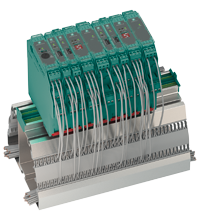
| Connection | terminals 23+, 24- or power feed module/Power Rail |
| Rated voltage | 20 ... 30 V DC |
| Rated current | approx. 130 mA |
| Power dissipation | 2.2 W |
| Power consumption | 2.5 W |
| Interface |
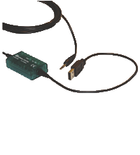
| Programming interface | programming socket |
| Input |
| Connection side | field side |
| Connection | input I: terminals 1+, 3-
input II: terminals 4+, 6-
input III: terminals 13+, 14- (control input 1)
input IV: terminals 15+, 14- (control input 2) |
| Input I, II | 2-wire sensor, sensor acc. to EN 60947-5-6 (NAMUR) or mechanical contact |
| Open circuit voltage/short-circuit current | 8.2 V / 10 mA |
| Switching point/switching hysteresis | logic 1: > 2.5 mA ; logic 0: < 1.9 mA |
| Pulse duration | min. 250 µs , overlap on direction of rotation signal: ≥ 125 µs |
| Input frequency | rotation direction monitoring 0.001 ... 1000 Hz slip monitoring 10 ... 1000 Hz |
| Line fault detection | breakage I ≤ 0.15 mA; short-circuit I > 4 mA |
| Input III, IV | |
| Active/Passive | I > 4 mA (for min. 100 ms) / I < 1.5 mA |
| Open circuit voltage/short-circuit current | 18 V / 5 mA |
| Output |
| Connection side | control side |
| Connection | output I: terminals 10, 11, 12
output II: terminals 16, 17, 18
output III: terminals 19+, 20-
output IV: terminals 21+, 20-
output V: terminals 7-, 8+ |
| Output I, II | signal, relay |
| Contact loading | 250 V AC / 2 A / cos φ ≥ 0.7 ; 40 DC / 2 A |
| Mechanical life | 5 x 10⁷ switching cycles |
| Energized/De-energized delay | approx. 20 ms / approx. 20 ms |
| Output III and IV | signal , electronic output, passive |
| Contact loading | 40 V DC |
| Signal level | 1-signal: (L+) -2.5 V (50 mA, short-circuit/overload proof)
0-signal: blocked output (off-state current ≤ 10 µA) |
| Output V | analog |
| Current range | 0 ... 20 mA or 4 ... 20 mA |
| Open loop voltage | max. 24 V DC |
| Load | max. 650 Ω |
| Fault signal | downscale I ≤ 3.6 mA, upscale I ≥ 21.5 mA (acc. NAMUR NE43) |
| Collective error message | Power Rail |
| Transfer characteristics |
| Input I and II | |
| Measurement range | 0.001 ... 1000 Hz |
| Resolution | slip monitoring: 1% frequency measurement: 0,1% of measured value; but >0.001Hz |
| Accuracy | slip monitoring: 1% frequency measurement: 0.5% of measured value; but >0.001Hz |
| Measuring time | frequency measurement: < 100 ms |
| Influence of ambient temperature | 0.003 %/K (30 ppm) |
| Output I, II | |
| Response delay | ≤ 200 ms |
| Output V | |
| Resolution | < 10 µA |
| Accuracy | < 30 µA |
| Influence of ambient temperature | 0.005 %/K (50 ppm) |
| Galvanic isolation |
| Input I, II/other circuits | reinforced insulation according to IEC/EN 61010-1, rated insulation voltage 300 Veff |
| Input III, IV/power supply and collective error | functional insulation acc. to IEC 62103, rated insulation voltage 50 Veff |
| Output I, II/other circuits | reinforced insulation according to IEC/EN 61010-1, rated insulation voltage 300 Veff |
| Mutual output I, II, III | reinforced insulation according to IEC/EN 61010-1, rated insulation voltage 300 Veff |
| Mutual output I, II, IV | reinforced insulation according to IEC/EN 61010-1, rated insulation voltage 300 Veff |
| Output III, IV/power supply and collective error | basic insulation according to IEC/EN 61010-1, rated insulation voltage 50 Veff |
| Output III, IV/input III, IV | basic insulation according to IEC/EN 61010-1, rated insulation voltage 50 Veff |
| Output III, IV/V | basic insulation according to IEC/EN 61010-1, rated insulation voltage 50 Veff |
| Output V/power supply and collective error | functional insulation acc. to IEC 62103, rated insulation voltage 50 Veff |
| Interface/power supply and collective error | functional insulation acc. to IEC 62103, rated insulation voltage 50 Veff |
| Interface/output III, IV | basic insulation according to IEC/EN 61010-1, rated insulation voltage 50 Veff |
| Indicators/settings |
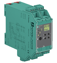
| Display elements | LEDs , display |
| Control elements | Control panel |
| Configuration | via operating buttons
via PACTware |
| Labeling | space for labeling at the front |
| Directive conformity |
| Electromagnetic compatibility | |
| Directive 2014/30/EU | EN 61326-1:2013 (industrial locations) |
| Low voltage | |
| Directive 2014/35/EU | EN 61010-1:2010 |
| Conformity |
| Electromagnetic compatibility | NE 21:2006 |
| Degree of protection | IEC 60529:2001 |
| Input | EN 60947-5-6:2000 |
| Ambient conditions |
| Ambient temperature | -20 ... 60 °C (-4 ... 140 °F) |
| Mechanical specifications |
| Degree of protection | IP20 |
| Connection | screw terminals |
| Mass | 300 g |
| Dimensions | 40 x 119 x 115 mm (1.6 x 4.7 x 4.5 inch) (W x H x D) , housing type C2 |
| Height | 119 mm |
| Width | 40 mm |
| Depth | 115 mm |
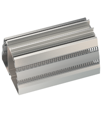
| Mounting | on 35 mm DIN mounting rail acc. to EN 60715:2001 |
| International approvals |
| UL approval | E223772 |
| General information |
| Supplementary information | Observe the certificates, declarations of conformity, instruction manuals, and manuals where applicable. For information see www.pepperl-fuchs.com. |


 +44 161 6336431