

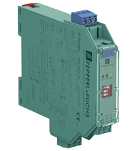
Switch Amplifier KFD2-SR2-Ex1.W
- 1-channel isolated barrier
- 24 V DC supply (Power Rail)
- Dry contact or NAMUR inputs
- Relay contact output
- Line fault detection (LFD)
- Reversible mode of operation
- Up to SIL 2 (SC 3) acc. to IEC/EN 61508


Please note: All product-related documents, such as certificates, declarations of conformity, etc., which were issued prior to the conversion under the name Pepperl+Fuchs GmbH or Pepperl+Fuchs AG, also apply to Pepperl+Fuchs SE.
Datasheet excerpt: Technical data of KFD2-SR2-Ex1.W
| General specifications | ||
|---|---|---|
| Signal type | Digital Input | |
| Functional safety related parameters | ||
| Safety Integrity Level (SIL) | SIL 2 | |
| Systematic capability (SC) | SC 3 | |
| Supply | ||
| Connection | Power Rail or terminals 14+, 15- | |
| Rated voltage | 19 ... 30 V DC | |
| Ripple | ≤ 10 % | |
| Rated current | ≤ 35 mA | |
| Power dissipation | ≤ 0.7 W | |
| Power consumption | ≤ 0.7 W | |
| Input | ||
| Connection side | field side | |
| Connection | terminals 1+, 2+, 3- | |
| Rated values | acc. to EN 60947-5-6 (NAMUR) | |
| Open circuit voltage/short-circuit current | approx. 8 V DC / approx. 8 mA | |
| Switching point/switching hysteresis | 1.2 ... 2.1 mA / approx. 0.2 mA | |
| Line fault detection | breakage I ≤ 0.1 mA , short-circuit I > 6 mA | |
| Pulse/Pause ratio | min. 20 ms / min. 20 ms | |
| Output | ||
| Connection side | control side | |
| Connection | terminals 7, 8, 9 | |
| Output | signal ; relay | |
| Contact loading | 250 V AC/2 A/cos φ > 0.75; 126.5 V AC/4 A/cos φ > 0.75; 40 V DC/2 A resistive load | |
| Minimum switch current | 2 mA / 24 V DC | |
| Energized/De-energized delay | approx. 20 ms / approx. 20 ms | |
| Mechanical life | 107 switching cycles | |
| Collective error message | Power Rail | |
| Transfer characteristics | ||
| Switching frequency | < 10 Hz | |
| Galvanic isolation | ||
| Input/Output | reinforced insulation according to IEC/EN 61010-1, rated insulation voltage 300 Veff | |
| Input/power supply | reinforced insulation according to IEC/EN 61010-1, rated insulation voltage 300 Veff | |
| Output/power supply | reinforced insulation according to IEC/EN 61010-1, rated insulation voltage 300 Veff | |
| Indicators/settings | ||
| Display elements | LEDs | |
| Control elements | DIP switch | |
| Configuration | via DIP switches | |
| Labeling | space for labeling at the front | |
| Directive conformity | ||
| Electromagnetic compatibility | ||
| Directive 2014/30/EU | EN 61326-1:2013 (industrial locations) | |
| Low voltage | ||
| Directive 2014/35/EU | EN 61010-1:2010+A1:2019+A1:2019/AC:2019 | |
| Conformity | ||
| Electromagnetic compatibility | NE 21:2017 , EN 61326-3-1:2017 , EN IEC 61326-3-2:2018 | |
| Degree of protection | IEC 60529:1989+A1:1999+A2:2013 | |
| Functional safety | IEC/EN 61508:2010 | |
| Input | EN 60947-5-6:2000 | |
| Ambient conditions | ||
| Ambient temperature | -40 ... 70 °C (-40 ... 158 °F) | |
| Mechanical specifications | ||
| Degree of protection | IP20 | |
| Connection | screw terminals | |
| Mass | approx. 150 g | |
| Dimensions | 20 x 119 x 115 mm (0.8 x 4.7 x 4.5 inch) (W x H x D) , housing type B2 | |
| Height | 119 mm | |
| Width | 20 mm | |
| Depth | 115 mm | |
| Mounting | on 35 mm DIN mounting rail acc. to EN 60715:2001 | |
| Data for application in connection with hazardous areas | ||
| EU-type examination certificate | PTB 00 ATEX 2080 | |
| Marking |  II (1)G [Ex ia Ga] IIC II (1)D [Ex ia Da] IIIC I (M1) [Ex ia Ma] I II (1)G [Ex ia Ga] IIC II (1)D [Ex ia Da] IIIC I (M1) [Ex ia Ma] I |
|
| Input | Ex ia | |
| Voltage | 10.5 V | |
| Current | 13 mA | |
| Power | 34 mW (linear characteristic) | |
| Supply | ||
| Maximum safe voltage | 253 V AC / 125 V DC (Attention! Um is no rated voltage.) | |
| Output | ||
| Maximum safe voltage | 253 V AC (Attention! The rated voltage can be lower.) | |
| Fault indication output | ||
| Maximum safe voltage | 40 V DC (Attention! Um is no rated voltage.) | |
| Certificate | PF 08 CERT 0803 | |
| Marking | II (3)G [Ex ic Gc] IIC |
|
| Input | Ex ic | |
| Voltage | 10.5 V | |
| Current | 13 mA | |
| Power | 34 mW (linear characteristic) | |
| Certificate | TÜV 99 ATEX 1493 X | |
| Marking | II 3G Ex ec nC IIC T4 Gc |
|
| Galvanic isolation | ||
| Input/Output | safe electrical isolation acc. to IEC/EN 60079-11, voltage peak value 375 V | |
| Input/power supply | safe electrical isolation acc. to IEC/EN 60079-11, voltage peak value 375 V | |
| Directive conformity | ||
| Directive 2014/34/EU | EN IEC 60079-0:2018+AC:2020 , EN 60079-7:2015+A1:2018 , EN 60079-11:2012 , EN IEC 60079-15:2019 | |
| International approvals | ||
| FM approval | ||
| FM certificate | FM19US0207X | |
| Control drawing | 116-0035 | |
| UL approval | E106378 | |
| Control drawing | 116-0473 (cULus) | |
| Contact loading | 250 V AC/2 A/cos φ > 0.75; 126.5 V AC/4 A/cos φ > 0.75; 30 V DC/2 A resistive load | |
| IECEx approval | ||
| IECEx certificate | IECEx PTB 11.0034 , IECEx TUN 19.0013X | |
| IECEx marking | [Ex ia Ga] IIC [Ex ia Da] IIIC [Ex ia Ma] I Ex ec nC IIC T4 Gc |
|
| General information | ||
| Supplementary information | Observe the certificates, declarations of conformity, instruction manuals, and manuals where applicable. For information see www.pepperl-fuchs.com. | |
Classifications
| System | Classcode |
|---|---|
| ECLASS 13.0 | 27210121 |
| ECLASS 12.0 | 27210121 |
| ECLASS 11.0 | 27210121 |
| ECLASS 10.0.1 | 27210121 |
| ECLASS 9.0 | 27210121 |
| ECLASS 8.0 | 27210121 |
| ECLASS 5.1 | 27210121 |
| ETIM 9.0 | EC001485 |
| ETIM 8.0 | EC001485 |
| ETIM 7.0 | EC001485 |
| ETIM 6.0 | EC001485 |
| ETIM 5.0 | EC001485 |
| UNSPSC 12.1 | 32101514 |
Details: KFD2-SR2-Ex1.W
This isolated barrier is used for intrinsic safety applications.
The device transfers digital signals from NAMUR sensors or dry contacts from the hazardous area to the non-hazardous area.
The proximity sensor or the mechanical contact controls the control side load for a relay contact output. The device output changes the state when the input signal changes the state.
Via switches the mode of operation can be reversed and the line fault detection can be switched off.
During a fault condition, the relay reverts to its de-energized state and the LEDs indicate the fault according to NAMUR NE 44.
If the device is operated via Power Rail, additionally a collective error message is available.
Datasheet: KFD2-SR2-Ex1.W
| Datasheet | File Type | File Size |
|---|---|---|
| Datasheet KFD2-SR2-Ex1.W | 1337 KB | |
| Fiche de données KFD2-SR2-Ex1.W | 1357 KB | |
| Datenblatt KFD2-SR2-Ex1.W | 1348 KB | |
| Datasheet KFD2-SR2-Ex1.W | 1445 KB | |
| Hoja de datos KFD2-SR2-Ex1.W | 1360 KB |
Documents: KFD2-SR2-Ex1.W
CAD+CAE: KFD2-SR2-Ex1.W
| CAD | File Type | File Size |
|---|---|---|
| CAD 3-D / CAD 3-D | STP | 2510 KB |
| CAD Portal / CAD Portal | LINK | --- |
| EPLAN | ||
| EPLAN macro EDZ / EPLAN Makro EDZ | EDZ | 65 KB |
Approvals+Certificates: KFD2-SR2-Ex1.W
| Certificates | File Type | File Size |
|---|---|---|
| Australia Test Safe | 6788 KB | |
| Brasil TUV Rheinland Brazil | 1155 KB | |
| China SITIIAS CCC Ex Certificate | 1101 KB | |
| DNV Marine | 114 KB | |
| Europe PTB ATEX Category (1) D ATEX Category (M1) ATEX Category (1) G | 554 KB | |
| Europe Pepperl+Fuchs ATEX Category 3 G | 160 KB | |
| Europe TUV II 3 G | 2538 KB | |
| India PESO (India) CCOE | 101 KB | |
| Japan TIIS | 2060 KB | |
| Korea KOSHA | 346 KB | |
| PTB IECEx Certificate of Conformity | LINK | --- |
| South Africa MASC | 527 KB | |
| South Africa MASC | 577 KB | |
| TUV Nord IECEx Certificate of Conformity | LINK | --- |
| USA Canada UL Hazardous Location cULus UL E106378 | 412 KB | |
| USA FM | 350 KB | |
| Ukraine SERTIS Ex | 12351 KB | |
| Worldwide TUV Rheinland Functional Safety Certificate | 620 KB | |
| Control Drawings | ||
| Control drawing FM / Control drawing FM | 130 KB | |
| Control drawing UL / Control drawing UL | 132 KB | |
| Declaration of Conformity | ||
| EU Declaration of Conformity (P+F) / EU-Konformitäterklärung (P+F) | 111 KB |
Associated Products: KFD2-SR2-Ex1.W
| Matching System Components | ||||||
|---|---|---|---|---|---|---|
|
||||||
|
||||||
|
||||||
|
||||||
|
||||||
|
||||||
| Accessories | ||||||
|
||||||
|
||||||
|
||||||
|
||||||


Choose from various selection criteria like safety integrity level, performance level, device function, and signal type and find the SIL/PL assessed device that you are looking for.


Pepperl+Fuchs GB Ltd.
77 Ripponden Road
Oldham OL1 4EL, Lancs.
United Kingdom
sales@gb.pepperl-fuchs.com
 +44 161 6336431
Pepperl+Fuchs is a leading developer and manufacturer of electronic sensors and components for the global automation market. Continuous innovation, enduring quality, and steady growth have been the foundation of our success for more than 70 years. Pepperl+Fuchs employs 6,300 people worldwide and has manufacturing facilities in Germany, USA, Singapore, Hungary, Indonesia and Vietnam, most of them ISO 9001 certified.