

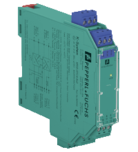
SMART Transmitter Power Supply KFD2-STC4-Ex2
- 2-channel isolated barrier
- 24 V DC supply (Power Rail)
- Input 2-wire SMART transmitters
- Output 0/4 mA ... 20 mA
- Terminals with test points
- Up to SIL 2 acc. to IEC/EN 61508


Please note: All product-related documents, such as certificates, declarations of conformity, etc., which were issued prior to the conversion under the name Pepperl+Fuchs GmbH or Pepperl+Fuchs AG, also apply to Pepperl+Fuchs SE.
Datasheet excerpt: Technical data of KFD2-STC4-Ex2
| General specifications | ||
|---|---|---|
| Signal type | Analog input | |
| Functional safety related parameters | ||
| Safety Integrity Level (SIL) | SIL 2 | |
| Supply | ||
| Connection | Power Rail or terminals 14+, 15- | |
| Rated voltage | 20 ... 35 V DC | |
| Ripple | within the supply tolerance | |
| Power dissipation | 1.8 W | |
| Power consumption | max. 2.7 W | |
| Input | ||
| Connection side | field side | |
| Connection | terminals 1+, 3-; 4+, 6- | |
| Input signal | 0/4 ... 20 mA | |
| Available voltage | ≥ 16 V at 20 mA, terminals 1+, 3 | |
| Output | ||
| Connection side | control side | |
| Connection | terminals 7-, 8+; 10-, 11+ | |
| Load | 0 ... 550 Ω at 20 mA | |
| Output signal | 0/4 ... 20 mA (overload > 25 mA) | |
| Ripple | max. 50 µA rms | |
| Transfer characteristics | ||
| Deviation | at 20 °C (68 °F), 0/4 ... 20 mA ≤ 10 µA incl. calibration, linearity, hysteresis, loads and fluctuations of supply voltage |
|
| Influence of ambient temperature | 0.25 µA/K | |
| Frequency range | field side into the control side: band width with 1 Vpp signal 0 ... 7.5 kHz (-3 dB) safe area to hazardous area: band width with 1 VSS signal 0.3 ... 7.5 kHz (-3 dB) |
|
| Settling time | 200 µs | |
| Rise time/fall time | 20 µs | |
| Galvanic isolation | ||
| Output/power supply | functional insulation, rated insulation voltage 50 V AC | |
| Output/Output | functional insulation, rated insulation voltage 50 V AC | |
| Indicators/settings | ||
| Display elements | LED | |
| Labeling | space for labeling at the front | |
| Directive conformity | ||
| Electromagnetic compatibility | ||
| Directive 2014/30/EU | EN 61326-1:2013 (industrial locations) | |
| Conformity | ||
| Electromagnetic compatibility | NE 21:2011 | |
| Degree of protection | IEC 60529:2001 | |
| Protection against electrical shock | UL 61010-1:2012 | |
| Ambient conditions | ||
| Ambient temperature | -20 ... 60 °C (-4 ... 140 °F) | |
| Mechanical specifications | ||
| Degree of protection | IP20 | |
| Connection | screw terminals | |
| Mass | approx. 150 g | |
| Dimensions | 20 x 124 x 115 mm (0.8 x 4.9 x 4.5 inch) , (W x H x D) housing type B2 | |
| Height | 124 mm | |
| Width | 20 mm | |
| Depth | 115 mm | |
| Mounting | on 35 mm DIN mounting rail acc. to EN 60715:2001 | |
| Data for application in connection with hazardous areas | ||
| EU-type examination certificate | BAS 99 ATEX 7025 X | |
| Marking |  II (1)G [Ex ia Ga] IIC , II (1)D [Ex ia Da] IIIC , I (M1) [Ex ia Ma] I II (1)G [Ex ia Ga] IIC , II (1)D [Ex ia Da] IIIC , I (M1) [Ex ia Ma] I |
|
| Input | [Ex ia Ga] IIC, [Ex ia Da] IIIC, [Ex ia Ma] I | |
| Voltage | 25.2 V | |
| Current | 93 mA | |
| Power | 0.586 W | |
| Supply | ||
| Maximum safe voltage | 250 V (Attention! The rated voltage can be lower.) | |
| Certificate | TÜV 99 ATEX 1499 X | |
| Marking | II 3G Ex nA II T4 |
|
| Galvanic isolation | ||
| Input/Output | safe electrical isolation acc. to IEC/EN 60079-11, voltage peak value 375 V | |
| Input/power supply | safe electrical isolation acc. to IEC/EN 60079-11, voltage peak value 375 V | |
| Directive conformity | ||
| Directive 2014/34/EU | EN IEC 60079-0:2018+AC:2020 , EN 60079-11:2012 , EN 60079-15:2010 | |
| International approvals | ||
| UL approval | E106378 | |
| Control drawing | 116-0428 (cULus) | |
| IECEx approval | ||
| IECEx certificate | IECEx BAS 04.0015X IECEx CML 15.0055X |
|
| IECEx marking | [Ex ia Ga] IIC , [Ex ia Da] IIIC , [Ex ia Ma] I Ex nA IIC T4 Gc |
|
| General information | ||
| Supplementary information | Observe the certificates, declarations of conformity, instruction manuals, and manuals where applicable. For information see www.pepperl-fuchs.com. | |
Classifications
| System | Classcode |
|---|---|
| ECLASS 13.0 | 27210119 |
| ECLASS 12.0 | 27210119 |
| ECLASS 11.0 | 27210119 |
| ECLASS 10.0.1 | 27210119 |
| ECLASS 9.0 | 27210119 |
| ECLASS 8.0 | 27210119 |
| ECLASS 5.1 | 27210119 |
| ETIM 9.0 | EC001485 |
| ETIM 8.0 | EC001485 |
| ETIM 7.0 | EC001485 |
| ETIM 6.0 | EC001485 |
| ETIM 5.0 | EC001485 |
| UNSPSC 12.1 | 32101514 |
Details: KFD2-STC4-Ex2
This isolated barrier is used for intrinsic safety applications.
The device supplies 2-wire SMART transmitters in a hazardous area.
It transfers the analog input signal to the safe area as an isolated current value.
Digital signals may be superimposed on the input signal in the hazardous or safe area and are transferred bi-directionally.
If the HART communication resistance in the loop is too low, the internal resistance of 250 Ω between terminals 8 and 9 can be used.
Test sockets for the connection of HART communicators are integrated into the terminals of the device.
Datasheet: KFD2-STC4-Ex2
| Datasheet | File Type | File Size |
|---|---|---|
| Datasheet KFD2-STC4-Ex2 | 311 KB | |
| Fiche de données KFD2-STC4-Ex2 | 1015 KB | |
| Datenblatt KFD2-STC4-Ex2 | 815 KB | |
| Datasheet KFD2-STC4-Ex2 | 1017 KB | |
| Hoja de datos KFD2-STC4-Ex2 | 1013 KB |
Documents: KFD2-STC4-Ex2
CAD+CAE: KFD2-STC4-Ex2
| CAD | File Type | File Size |
|---|---|---|
| CAD 3-D / CAD 3-D | STP | 3048 KB |
| CAD Portal / CAD Portal | LINK | --- |
| EPLAN | ||
| EPLAN macro EDZ / EPLAN Makro EDZ | EDZ | 61 KB |
Approvals+Certificates: KFD2-STC4-Ex2
| Certificates | File Type | File Size |
|---|---|---|
| Australia SIMTARS | 359 KB | |
| Baseefa IECEx Certificate of Conformity | LINK | --- |
| CML IECEx Certificate of Conformity Zone 2 | LINK | --- |
| China SITIIAS CCC Ex Certificate | 1112 KB | |
| DNV Marine | 114 KB | |
| Europe Baseefa ATEX Category (1) GD | 3124 KB | |
| Europe TUV Nord ATEX Category 3 G | 1999 KB | |
| India PESO (India) CCOE | 551 KB | |
| Japan TIIS | 2034 KB | |
| Korea KOSHA | 283 KB | |
| USA Canada UL Hazardous Location Certificate of Compliance cULus UL E106378 | 409 KB | |
| exida Functional Safety Assessment Summary | 349 KB | |
| Control Drawings | ||
| Control drawing UL / Control drawing UL | 28 KB | |
| Declaration of Conformity | ||
| EU Declaration of Conformity (P+F) / EU-Konformitäterklärung (P+F) | 83 KB |
Associated Products: KFD2-STC4-Ex2
| Matching System Components | ||||||
|---|---|---|---|---|---|---|
|
||||||
|
||||||
|
||||||
|
||||||
|
||||||
|
||||||
| Accessories | ||||||
|
||||||
|
||||||
|
||||||
|
||||||
|
||||||
|
||||||


Choose from various selection criteria like safety integrity level, performance level, device function, and signal type and find the SIL/PL assessed device that you are looking for.


Pepperl+Fuchs GB Ltd.
77 Ripponden Road
Oldham OL1 4EL, Lancs.
United Kingdom
sales@gb.pepperl-fuchs.com
 +44 161 6336431
Pepperl+Fuchs is a leading developer and manufacturer of electronic sensors and components for the global automation market. Continuous innovation, enduring quality, and steady growth have been the foundation of our success for more than 70 years. Pepperl+Fuchs employs 6,300 people worldwide and has manufacturing facilities in Germany, USA, Singapore, Hungary, Indonesia and Vietnam, most of them ISO 9001 certified.