

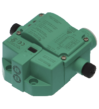
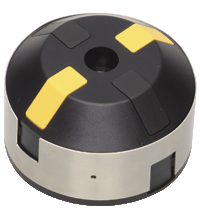
Inductive sensor NCN3-F31K-N4-V1-V1
- Direct mounting on standard actuators
- Fixed setting
- Usable up to SIL 2 acc. to IEC 61508
- LEDs for switching state of sensor and solenoid valve
- Valve LEDs disconnectable
- ATEX & IECEX certifications
NAMUR -antureita on käytettävä hyväksyttyjen kytkinvahvistimien kanssa. Löydät sopivat laitteet alta:


Please note: All product-related documents, such as certificates, declarations of conformity, etc., which were issued prior to the conversion under the name Pepperl+Fuchs GmbH or Pepperl+Fuchs AG, also apply to Pepperl+Fuchs SE.
Lataa koko tietolomake PDF-tiedostona:
Ote tietolomakkeesta: Tekniset tiedot NCN3-F31K-N4-V1-V1
| General specifications | ||
|---|---|---|
| Switching function | 2 x normally closed (NC) | |
| Output type | NAMUR | |
| Rated operating distance | 3 mm | |
| Installation | flush mountable | |
| Assured operating distance | 0 ... 2.4 mm | |
| Actual operating distance | 2.7 ... 3.3 mm typ. | |
| Actuating element | Stainless steel 1.4305 / AISI 303 8.5 mm x 8.5 mm x 0.5 mm |
|
| Reduction factor rAl | 0.5 | |
| Reduction factor rCu | 0.4 | |
| Reduction factor r304 | 1 | |
| Reduction factor rSt37 | 1.3 | |
| Reduction factor rBrass | 0.6 | |
| Output type | 2-wire | |
| Nominal ratings | ||
| Nominal voltage | 8.2 V (Ri approx. 1 kΩ) | |
| Switching frequency | 0 ... 3 kHz | |
| Hysteresis | typ. 5 % | |
| Reverse polarity protection | reverse polarity protected | |
| Short-circuit protection | yes | |
| Suitable for 2:1 technology | yes , Reverse polarity protection diode not required | |
| Current consumption | ||
| Measuring plate not detected | ≥ 3 mA | |
| Measuring plate detected | ≤ 1 mA | |
| Time delay before availability | ≤ 1.1 ms | |
| Switching state indicator | LED, yellow | |
| Valve status indicator | LED, yellow | |
| Functional safety related parameters | ||
| Safety Integrity Level (SIL) | SIL 2 | |
| MTTFd | 1470 a | |
| Mission Time (TM) | 20 a | |
| Diagnostic Coverage (DC) | 0 % | |
| Valve circuit | ||
| Voltage | max. 32 V DC | |
| Current | max. 240 mA | |
| Short-circuit protection | no | |
| Reverse polarity protection | yes, with reversed output LED is out of function, therfore more power for solenoid valve | |
| Compliance with standards and directives | ||
| Standard conformity | ||
| NAMUR | EN 60947-5-6:2000 IEC 60947-5-6:1999 |
|
| Electromagnetic compatibility | NE 21:2007 | |
| Standards | EN 60947-5-2:2007 EN 60947-5-2/A1:2012 IEC 60947-5-2:2007 IEC 60947-5-2 AMD 1:2012 |
|
| Approvals and certificates | ||
| IECEx approval | ||
| Equipment protection level Ga | IECEx TUN 17.0021X | |
| Equipment protection level Gb | IECEx TUN 17.0021X | |
| Equipment protection level Mb | IECEx TUN 17.0021X | |
| ATEX approval | ||
| Equipment protection level Ga | TÜV 99 ATEX 1479 X | |
| Equipment protection level Gb | TÜV 99 ATEX 1479 X | |
| Equipment protection level Gc (ic) | PF13CERT2895 X | |
| UL approval | cULus Listed, General Purpose | |
| Ordinary Location | E87056 | |
| Hazardous Location | E501628 | |
| Control drawing | 116-0456 | |
| CCC approval | ||
| Hazardous Location | 2020322315002262 | |
| NEPSI approval | ||
| NEPSI certificate | GYJ19.1410X | |
| Ambient conditions | ||
| Ambient temperature | -25 ... 100 °C (-13 ... 212 °F) | |
| Storage temperature | -40 ... 100 °C (-40 ... 212 °F) | |
| Mechanical specifications | ||
| Connection (system side) | Cage tension spring terminals Stripped length 7 mm M20 x 1.5 cable gland usable thread length 11.5 mm screw-in depth max. 11.5 mm |
|
| Core cross section (system side) | Flexible: 0.2 ... 1.5 mm2 rigid: 0.2 ... 2.5 mm2 |
|
| Connection (valve side) | 4-pin, M12 x 1 socket | |
| Housing material | PBT | |
| Sensing face | PBT | |
| Degree of protection | IP67 | |
| Tightening torque, fastening screws | 4 Nm ... 5 Nm | |
| Tightening torque, housing screws | 1 Nm | |
| Tightening torque, cable gland | M20 x 1.5 ; max. 7 Nm | |
| Dimensions | ||
| Height | 35.5 mm | |
| Width | 65 mm | |
| Length | 77.5 mm | |
| Note | LED switch-off | |
| General information | ||
| Use in the hazardous area | see instruction manuals | |
Classifications
| System | Classcode |
|---|---|
| ECLASS 13.0 | 27273901 |
| ECLASS 12.0 | 27273901 |
| ECLASS 11.0 | 27220501 |
| ECLASS 10.0.1 | 27220501 |
| ECLASS 9.0 | 27220501 |
| ECLASS 8.0 | 27220501 |
| ECLASS 5.1 | 27220501 |
| ETIM 9.0 | EC002714 |
| ETIM 8.0 | EC002714 |
| ETIM 7.0 | EC002714 |
| ETIM 6.0 | EC002714 |
| ETIM 5.0 | EC002714 |
| UNSPSC 12.1 | 39121550 |
Details: NCN3-F31K-N4-V1-V1
Product Documentation: NCN3-F31K-N4-V1-V1
| Safety and Security Documentation | Kieli | Tiedostotyyppi | Tiedoston koko |
|---|---|---|---|
| Käyttöohje | FIN | 179 KB |
Design / Simulation: NCN3-F31K-N4-V1-V1
| CAD | Kieli | Tiedostotyyppi | Tiedoston koko |
|---|---|---|---|
| CAD Portal / CAD Portal | ALL | LINK | --- |
| CAD-files 3-D / CAD-Dateien 3-D | ALL | STP | 999 KB |
| CAE | |||
| CAE EPLAN macro EDZ / CAE EPLAN Makro EDZ | ALL | EDZ | 269 KB |
Approvals: NCN3-F31K-N4-V1-V1
| Certificates | Sertifikaatin nro | Kieli | Tiedostotyyppi | Tiedoston koko |
|---|---|---|---|---|
| Canada USA UL Hazardous Location | E501628:1:6 | ALL | 474 KB | |
| Canada USA UL Ordinary Location | UL-US-2140224-1 / UL-CA-2133715-1 | ALL | 491 KB | |
| China NEPSI | GYJ19.1410X | ALL | 2028 KB | |
| China SITIIAS CCC Ex Certificate | 2020322315002262 (Trutnov) | ALL | 2855 KB | |
| EU Pepperl+Fuchs Certificate Ex ic ATEX Category 3 G | PF13CERT2895X | ALL | 123 KB | |
| EU TUV Nord ATEX ia 2G, 1G, 1D s. certificate | TÜV 99 ATEX 1479 X | ALL | 662 KB | |
| United Kingdom CML UKEX Category I M2 UKEX Category II 2 G UKEX Category II 1 D UKEX Category II 1 G | CML 21UKEX21289X | ALL | 298 KB | |
| Worldwide Pepperl+Fuchs Functional Safety Certificate | PF12CERT2382G | ALL | 1492 KB | |
| Worldwide TUV Nord IECEx ia | IECEx TUN 17.0021X | ALL | LINK | --- |
| Control Drawings | ||||
| Control drawing UL / Control drawing UL | ALL | 378 KB | ||
| Declaration of Conformity | ||||
| EU Declaration of Conformity (P+F) / EU-Konformitäterklärung (P+F) | DOC-5076A | ALL | 1232 KB | |
| UK Declaration of Conformity (P+F) | TDOC-6562AENG | ENG | 1229 KB | |
Liitännäistuotteet: NCN3-F31K-N4-V1-V1
| Accessories | ||||||
|---|---|---|---|---|---|---|
|
||||||
|
||||||
|
||||||
|
||||||
|
||||||
|
||||||
|
||||||

Our amplify article gives interesting insights about the development of the new, modern portfolio of inductive proximity sensors from Pepperl+Fuchs. Get the whole story here!

The knowledge base for inductive sensors contains extensive expertise and supports you in the highly precise and smooth operation of the sensors in your machinery and plants.

The VariKont inductive sensors with Active Shielding Technology ensure high switching distances, no matter the installation situation and the surrounding material. Benefit from easier equipment design and reduced costs!
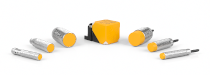
As the SIL 2/PL d inductive safety sensors have no dead band, data transfer can occur with no minimum distance between sensor and target. Discover the optimized portfolio for demanding environments.


Pepperl+Fuchs Oy
Areenakatu 7
FI-37570 Lempäälä
Finland
info@fi.pepperl-fuchs.com
 +358 20 7861 290
info@fi.pepperl-fuchs.com
+358 20 7861 291
Pepperl+Fuchs on dynaaminen ja tulevaisuuteen suuntaava yritys joka myy konepajateollisuuden, robotiikan ja teollisuusautomaation komponentteja. Tuotannon sujuvuus, tuotteiden korkea laatu ja niiden maailmanlaajuinen saatavuus ovat tuoneet yritykselle menestystä jo yli 70 vuoden ajan. Pepperl+Fuchs työllistää maailman laajuisesti yhteensä noin 6300 henkilöä. Globaalilla yrityksellä on tuotantolaitoksia Saksassa, Singaporessa, Yhdysvalloissa, Unkarissa, Indonesiassa ja Vietnamissa, joista suurin osa ovat ISO 9001-sertifioitu.