

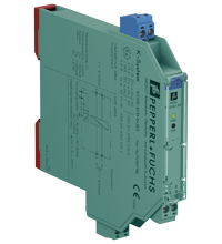
SMART Current Driver KCD2-SCD-Ex1.ES
- 1-channel isolated barrier
- 24 V DC supply (Power Rail)
- Current output up to 650 Ω load
- HART-IP and valve positioner
- Line fault detection (LFD)
- Housing width 12.5 mm
- Up to SIL 3 acc. to IEC/EN 61508


Please note: All product-related documents, such as certificates, declarations of conformity, etc., which were issued prior to the conversion under the name Pepperl+Fuchs GmbH or Pepperl+Fuchs AG, also apply to Pepperl+Fuchs SE.
Lataa koko tietolomake PDF-tiedostona:
Ote tietolomakkeesta: Tekniset tiedot KCD2-SCD-Ex1.ES
| General specifications | ||
|---|---|---|
| Signal type | Analog output | |
| Functional safety related parameters | ||
| Safety Integrity Level (SIL) | SIL 3 | |
| Supply | ||
| Connection | Power Rail or terminals 9+, 10- | |
| Rated voltage | 19 ... 30 V DC | |
| Ripple | ≤ 10 % | |
| Rated current | ≤ 33 mA at 24 V | |
| Power dissipation | ≤ 700 mW at 20 mA and 500 Ω load | |
| Power consumption | ≤ 800 mW | |
| Input | ||
| Connection side | control side | |
| Connection | terminals 5-, 6+ | |
| Input signal | 4 ... 20 mA , limited to approx. 25 mA | |
| Input voltage | open loop voltage of the control system < 30 V | |
| Voltage drop | approx. 6 V at 20 mA | |
| Input resistance | > 100 kΩ, with field wiring open or < 50 Ω | |
| Output | ||
| Connection side | field side | |
| Connection | terminals 1+, 2- | |
| Voltage | ≥ 13 V at 20 mA | |
| Current | 4 ... 20 mA | |
| Load | 100 ... 650 Ω | |
| Ripple | 20 mV rms | |
| Line fault detection | field wiring open or < 50 Ω and test current < 2 mA | |
| Transfer characteristics | ||
| Deviation | at 20 °C (68 °F), 4 ... 20 mA < 0.1 % of full scale, incl. non-linearity and hysteresis |
|
| Influence of ambient temperature | < 2 µA/K (-20 ... 70 °C (-4 ... 158 °F)); < 4 µA/K (-40 ... -20 °C (-40 ... -4 °F)) | |
| Frequency range | field side into the control side: bandwidth with 0.5 Vpp signal 0 ... 3 kHz (-3 dB) control side into the field side: bandwidth with 1 mApp signal 0 ... 3 kHz (-3 dB) |
|
| Rise time | 10 to 90 % ≤ 10 ms | |
| Galvanic isolation | ||
| Input/Output | basic insulation according to IEC/EN 61010-1, rated insulation voltage 300 Veff | |
| Input/power supply | basic insulation according to IEC/EN 61010-1, rated insulation voltage 300 Veff | |
| Output/power supply | reinforced insulation according to IEC/EN 61010-1, rated insulation voltage 300 Veff | |
| Indicators/settings | ||
| Display elements | LEDs | |
| Labeling | space for labeling at the front | |
| Directive conformity | ||
| Electromagnetic compatibility | ||
| Directive 2014/30/EU | EN 61326-1:2013 (industrial locations) | |
| Conformity | ||
| Electromagnetic compatibility | NE 21:2017 EN 61326-3-2:2018 |
|
| Degree of protection | IEC 60529 | |
| Protection against electrical shock | UL 61010-1:2012 | |
| Ambient conditions | ||
| Ambient temperature | -40 ... 70 °C (-40 ... 158 °F) | |
| Mechanical specifications | ||
| Degree of protection | IP20 | |
| Connection | screw terminals | |
| Mass | approx. 100 g | |
| Dimensions | 12.5 x 124 x 114 mm (0.5 x 4.9 x 4.5 inch) (W x H x D) , housing type A2 | |
| Height | 124 mm | |
| Width | 12.5 mm | |
| Depth | 114 mm | |
| Mounting | on 35 mm DIN mounting rail acc. to EN 60715:2001 | |
| Data for application in connection with hazardous areas | ||
| EU-type examination certificate | CESI 20 ATEX 016 X | |
| Marking |  II (1)G [Ex ia Ga] IIC II (1)D [Ex ia Da] IIIC I (M1) [Ex ia Ma] I II (1)G [Ex ia Ga] IIC II (1)D [Ex ia Da] IIIC I (M1) [Ex ia Ma] I |
|
| Output | Ex ia | |
| Supply | ||
| Maximum safe voltage | 250 V AC (Attention! Um is no rated voltage.) | |
| Equipment | terminals 1+, 2- | |
| Voltage | 25.2 V | |
| Current | 100 mA | |
| Power | 630 mW | |
| Internal capacitance | 5.7 nF | |
| Internal inductance | negligible | |
| Certificate | CESI 20 ATEX 017 X | |
| Marking | II 3G Ex ec IIC T4 Gc |
|
| Galvanic isolation | ||
| Input/Output | safe electrical isolation acc. to IEC/EN 60079-11, voltage peak value 375 V | |
| Output/power supply | safe electrical isolation acc. to IEC/EN 60079-11, voltage peak value 375 V | |
| Directive conformity | ||
| Directive 2014/34/EU | EN IEC 60079-0:2018 , EN 60079-11:2012 , EN 60079-7:2015 | |
| International approvals | ||
| UL approval | E106378 | |
| Control drawing | 116-0471 (cULus) | |
| IECEx approval | ||
| IECEx certificate | IECEx CES 20.0009X | |
| IECEx marking | [Ex ia Ga] IIC , [Ex ia Da] IIIC , [Ex ia Ma] I Ex ec IIC T4 Gc |
|
| General information | ||
| Supplementary information | Observe the certificates, declarations of conformity, instruction manuals, and manuals where applicable. For information see www.pepperl-fuchs.com. | |
Classifications
| System | Classcode |
|---|---|
| ECLASS 13.0 | 27210120 |
| ECLASS 12.0 | 27210120 |
| ECLASS 11.0 | 27210120 |
| ECLASS 10.0.1 | 27210120 |
| ECLASS 9.0 | 27210120 |
| ECLASS 8.0 | 27210120 |
| ECLASS 5.1 | 27210120 |
| ETIM 9.0 | EC002653 |
| ETIM 8.0 | EC002653 |
| ETIM 7.0 | EC002653 |
| ETIM 6.0 | EC002653 |
| ETIM 5.0 | EC001485 |
| UNSPSC 12.1 | 32101514 |
Details: KCD2-SCD-Ex1.ES
Function
This isolated barrier is used for intrinsic safety applications.
The device repeats the input signal from a control system to drive HART I/P converters, electrical valves, and positioners located in a hazardous area.
Digital signals are superimposed on the analog values at the field side or control side and are transferred bi-directionally.
The current is transferred via a DC/DC converter and repeated at the output terminals.
An open or short field circuit presents a high impedance to the control side to allow alarm conditions to be monitored by the control system.
Test sockets for the connection of HART communicators are integrated into the terminals of the device.
A fault is signalized by LEDs and a separate collective error message output.
Informative Literature: KCD2-SCD-Ex1.ES
| Literature | Kieli | Tiedostotyyppi | Tiedoston koko |
|---|---|---|---|
| Application Report - Energy Generation in Wastwater Treatment Plants | ENG | 532 KB | |
| Application Report - Generating Electricity in Coal-Fired Power Plants | ENG | 412 KB | |
| Application Report - Screening Systems in Sewage Treatment Plants | ENG | 577 KB | |
| Application Report - Sicherer Brennstofftransport in Kohlekraftwerken | ENG | 391 KB | |
| Application Report - Water Inlet in Wastewater Treatment Plants | ENG | 526 KB |
Product Documentation: KCD2-SCD-Ex1.ES
| Safety and Security Documentation | Kieli | Tiedostotyyppi | Tiedoston koko |
|---|---|---|---|
| Käyttöohje | FIN | 143 KB | |
| Functional Safety Manual | ENG | 1973 KB | |
| Manuals | |||
| Manual | ENG | 3685 KB | |
Design / Simulation: KCD2-SCD-Ex1.ES
| CAD | Kieli | Tiedostotyyppi | Tiedoston koko |
|---|---|---|---|
| CAD 3-D / CAD 3-D | ALL | STP | 3087 KB |
| CAD Portal / CAD Portal | ALL | LINK | --- |
| CAE | |||
| CAE EPLAN Data Portal / CAE EPLAN Data Portal | ALL | LINK | --- |
| CAE EPLAN macro EDZ / CAE EPLAN Makro EDZ | ALL | EDZ | 1522 KB |
Approvals: KCD2-SCD-Ex1.ES
| Certificates | Sertifikaatin nro | Kieli | Tiedostotyyppi | Tiedoston koko |
|---|---|---|---|---|
| CESI IECEx Certificate of Conformity | IECEx CES 20.0009X | ALL | LINK | --- |
| Canada, USA UL Hazardous Location Certificate of Compliance cULus UL E106378 | CoC E106378 - RepRef E106378-20200309 | ALL | 414 KB | |
| DNV Marine | TAA00001WX | ALL | 106 KB | |
| Europe CESI ATEX ATEX Category (M1) ATEX Category (1) D ATEX Category (1) G | CESI 20 ATEX 016X | ALL | 423 KB | |
| Europe CESI ATEX Category 3 G | CESI 20 ATEX 017X | ALL | 368 KB | |
| Worldwide TUV Functional Safety Certificate | No. 20 19716 | ALL | 366 KB | |
| Control Drawings | ||||
| Control drawing UL / Control drawing UL | ALL | 27 KB | ||
| Declaration of Conformity | ||||
| EU Declaration of Conformity (P+F) / EU-Konformitäterklärung (P+F) | DOC-4819A | ALL | 81 KB | |
Liitännäistuotteet: KCD2-SCD-Ex1.ES
| Matching System Components | ||||||
|---|---|---|---|---|---|---|
|
||||||
|
||||||
|
||||||
|
||||||
|
||||||
|
||||||
| Accessories | ||||||
|
||||||
|
||||||
|
||||||


Pepperl+Fuchs Oy
Areenakatu 7
FI-37570 Lempäälä
Finland
info@fi.pepperl-fuchs.com
 +358 20 7861 290
info@fi.pepperl-fuchs.com
+358 20 7861 291
Pepperl+Fuchs on dynaaminen ja tulevaisuuteen suuntaava yritys joka myy konepajateollisuuden, robotiikan ja teollisuusautomaation komponentteja. Tuotannon sujuvuus, tuotteiden korkea laatu ja niiden maailmanlaajuinen saatavuus ovat tuoneet yritykselle menestystä jo yli 70 vuoden ajan. Pepperl+Fuchs työllistää maailman laajuisesti yhteensä noin 6300 henkilöä. Globaalilla yrityksellä on tuotantolaitoksia Saksassa, Singaporessa, Yhdysvalloissa, Unkarissa, Indonesiassa ja Vietnamissa, joista suurin osa ovat ISO 9001-sertifioitu.