

Connection Methods
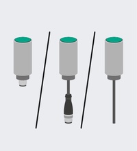
Inductive sensors can be integrated into systems in various ways. The various versions of sensors with fixed cables with or without plugs or with connector plugs are available as standard in various designs.
Terminal Compartment
Sensors of this type have a designated area in the sensor housing for electrically interconnecting the sensor to the plant. The terminal compartment allows users to freely select the connection cable. This is of particular benefit in applications involving UV resistance or resistance to chemical agents. In addition, users are not tied to fixed cable lengths, and the terminal compartment offers increased tamper protection compared to versions with connectors.
Pepperl+Fuchs inductive sensors with terminal compartments may contain the type designation "KK" in the second position of the type code.
Fixed Cable with or without Connector
Sensors of this type have a fixed cable that can be preassembled or a fixed cable with a typical connector for industrial automation. Sensors with fixed cable are affordable options, since they do not require an additional single-ended female cordset and keep the number of connection points to a minimum. Connection to special connectors is possible depending on the application requirement (e.g., automotive industry).
Sensors with fixed cables and a connector have information on the cable length and the type of connector included at the end of their type code, e.g.: NBB0,8-4M25-E2-0,3M-V3, NMB1,5-8GM35-E2-FE-150MM-V1, etc.
Connectors for Data Transfer
Inductive sensors are available with a standard selection of industrial automation connectors, including M8 and M12, 1/2 inch and 7/8 inch. When replacing the sensor, the cabling does not need to be replaced completely. This prevents error-prone new connections in the terminal compartment. Standardized single-ended female cordsets are available in the Pepperl+Fuchs accessories range.
Inductive sensors with these connection options have one of the following type designations at the end of the type code: V1, V3, V5, V13, V16, V18.
Other Connections
In addition to other versions, e.g., FASTON® connectors or sensors with solder connections are available.
Electrical Versions and Basic Circuit Diagrams
The following table provides an overview of common inductive sensors with regard to the electrical version, sensor type, typical data, and the basic circuit diagram.
| Direct-Current Voltage 10 V ... 60 V | |
|---|---|
| Sensor type |
|
| Wiring diagram according to EN 60947-5-2 |
NO contact or NC contact
Example: NO contact Z/Z0 |
| Typical data |
|
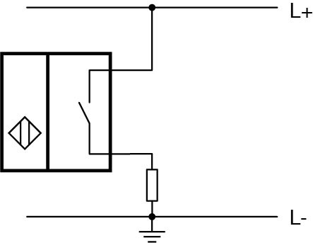
| Basic Series 10 V ... 30 V, 100 mA Standard Series 10 V ... 60 V, 200 mA |
|
|---|---|
| Sensor type |
|
| Wiring diagram according to EN 60947-5-2 |
NO contact or NC contact
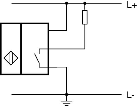 Example: NO contact E/E0
|
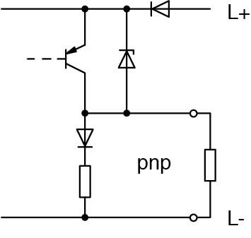
| Basic circuit diagram | 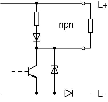 |
 |
|
| Typical data |
|
| Sensor type |
|
| Wiring diagram according to EN 60947-5-2 |
NC contact and NO contact
 Example: NC contact and NO contact A2
|
| Typical data |
|
| Alternating-Current Voltage 20 V ... 250 V | |
|---|---|
| Sensor type | WS, WÖ, W, W4 |
| Wiring diagram according to EN 60947-5-2 |
NC contact and NO contact
 Example: NC contact WÖ/UÖ
|
| Typical data |
|
| Universal Current 20 V ... 250 V AC, 45 Hz ... 65 Hz, 30 V ... 300 V DC | |
|---|---|
| Sensor type | US, UÖ |
| Wiring diagram according to EN 60947-5-2 |
NC contact and NO contact
Example: NC contact WÖ/UÖ |
| Typical data |
|
| Direct-Current Voltage 8 V DC | |
|---|---|
| Sensor type |
|
| Wiring diagram according to EN 60947-5-2 |
NC contact or NO contact
 Example: NC contact N/N0 or SN
|
| Typical data |
|
Sensor Types: Wire Colors and Plug Assignment According to EN 60947-5-2
Below you find an overview of the pin assignment and wire colors of the inductive sensors.
The pinout numbers correspond to the numbering of the pins on the connector plugs. This does not apply to proximity sensors for AC and those with 3-pin 8 mm plugs.
Switches without protective insulation require a protective conductor terminal for voltages above 50 V AC and 120 V DC.
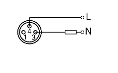
| 2 AC Connections | ||
|---|---|---|
| Function | NO contact | |
| Connection/wire color | ./. Use any color except yellow/green or yellow. Ensure both wires have the same color. |
|
| Pinout | 3 | 4 | |
| V1 connector plug | 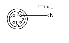 |
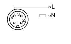 |
| V13 connector plug | 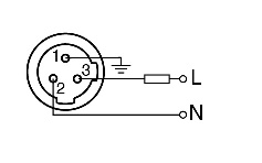 |
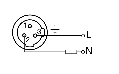 |
| V3 connector plug | 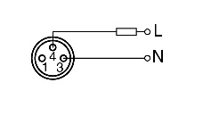 |
 |
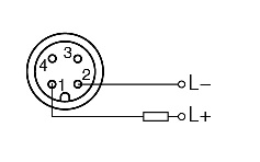
| 2 DC Connections—Free Polarity | ||
|---|---|---|
| Function | NC contact | |
| Connection/wire color | + | - ./. |
|
| Pinout | 1 | 2 | |
| V1 connector plug |  |
 |
| V13 connector plug | 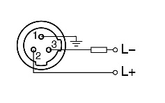 |
 |
| 2 DC Connections—Observe Polarity | ||
|---|---|---|
| Function | NO contact | |
| Connection/wire color | + | - Brown (BN) | Blue (BU) |
|
| Pinout | 1 | 4 | |
| V1 connector plug | 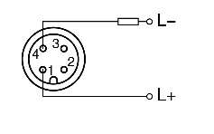 |
 |
| V3 connector plug | 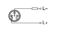 |
 |
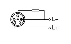
| 2 DC Connections—Observe Polarity | ||
|---|---|---|
| Function | NC contact | |
| Connection/wire color | + | - Brown (BN) | Blue (BU) |
|
| Pinout | 1 | 2 | |
| V1 connector plug | 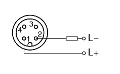 |
 |
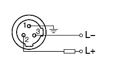
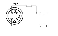
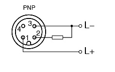
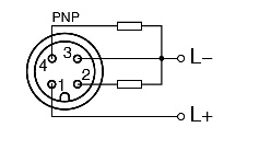
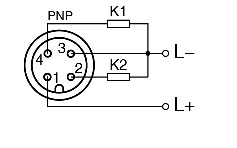
| 3 DC Connections—Observe Polarity | ||
|---|---|---|
| Function | NO contact | |
| Connection/wire color | + | - | output Brown (BN) | Blue (BU) | Black (BK) |
|
| Pinout | 1 | 3 | 4 | |
| V1 connector plug | 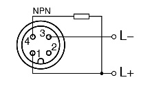 |
 |
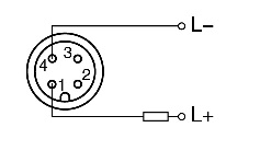
| Function | NC contact | |
| Connection/wire color | + | - | output Brown (BN) | Blue (BU) | Black (BK) |
|
| Pinout | 1 | 3 | 2 | |
| V1 connector plug | 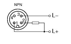 |
 |
| V3 connector plug | 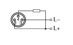 |
 |
| 4 DC Connections—Observe Polarity | ||
|---|---|---|
| Function | Change-over contact (open/close) | |
| Connection/wire color | + | - | NO contact output | NC contact output Brown (BN) | Blue (BU) | Black (BK) | White (WH) |
|
| Pinout | 1 | 3 | 4 | 2 | |
| V1 connector plug | 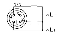 |
 |
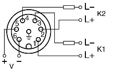
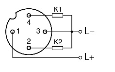
| 2 DC and NAMUR Connections—Observe Polarity | ||
|---|---|---|
| Function | NO contact and NC contact | |
| Connection/wire color | Channel 1+ | Channel 1- | Channel 2+ | Channel 2- | Valve + | Valve - Brown (BN) | Blue (BU) | White (WH) | Black (BK) | Red (RD) | Yellow (YE) |
|
| Pinout | 1 | 3 | 2 | 4 | 5 | 6 | |
| V1 connector plug | 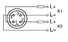 |
 |
| V16 connector plug | 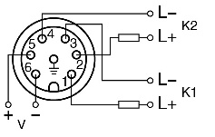 |
 |
| V18 connector plug | 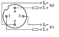 |
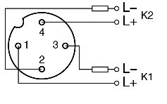 |
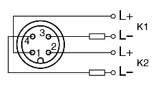
| 3 DC Connections—Observe Polarity | ||
|---|---|---|
| Function | NO contact and NC contact | |
| Connection/wire color | Power supply + | Power supply - | Output channel 1 | Output channel 2 Brown (BN) | Blue (BU) | Black (BK) | White (WH) |
|
| Pinout | 1 | 3 | 4 | |
| V1 connector plug |
K1 = Channel 1 |
|
| V18 connector plug |
K1 = Channel 1 |
|


Pepperl+Fuchs SE
Lilienthalstraße 200
68307 Mannheim
Germany
info@de.pepperl-fuchs.com
 +49 621 776-0
Pepperl+Fuchs is a leading developer and manufacturer of electronic sensors and components for the global automation market. Continuous innovation, enduring quality, and steady growth have been the foundation of our success for more than 70 years. Pepperl+Fuchs employs 6,300 people worldwide and has manufacturing facilities in Germany, USA, Singapore, Hungary, Indonesia and Vietnam, most of them ISO 9001 certified.