

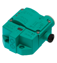
Inductive sensor NCN3-F31K-N4-K
- Direct mounting on standard actuators
- Fixed setting
- EC-Type Examination Certificate TÜV99 ATEX 1479X
- Usable up to SIL 2 acc. to IEC 61508
- LEDs for switching state of sensor and solenoid valve
- Valve LEDs disconnectable
- ATEX & IECEX certifications
NAMUR sensors must be operated with approved switch amplifiers. Please find suitable devices below:


Please note: All product-related documents, such as certificates, declarations of conformity, etc., which were issued prior to the conversion under the name Pepperl+Fuchs GmbH or Pepperl+Fuchs AG, also apply to Pepperl+Fuchs SE.
Download the complete datasheet as a PDF:
Datasheet excerpt: Technical data of NCN3-F31K-N4-K
| General specifications | ||
|---|---|---|
| Switching function | 2 x normally closed (NC) | |
| Output type | NAMUR | |
| Rated operating distance | 3 mm | |
| Installation | flush mountable | |
| Assured operating distance | 0 ... 2.4 mm | |
| Actual operating distance | 2.7 ... 3.3 mm typ. | |
| Actuating element | Stainless steel 1.4305 / AISI 303 8.5 mm x 8.5 mm x 0.5 mm |
|
| Reduction factor rAl | 0.5 | |
| Reduction factor rCu | 0.4 | |
| Reduction factor r304 | 1 | |
| Reduction factor rSt37 | 1.3 | |
| Reduction factor rBrass | 0.6 | |
| Output type | 2-wire | |
| Nominal ratings | ||
| Nominal voltage | 8.2 V (Ri approx. 1 kΩ) | |
| Switching frequency | 0 ... 3 kHz | |
| Hysteresis | typ. 5 % | |
| Reverse polarity protection | reverse polarity protected | |
| Short-circuit protection | yes | |
| Suitable for 2:1 technology | yes , Reverse polarity protection diode not required | |
| Current consumption | ||
| Measuring plate not detected | ≥ 3 mA | |
| Measuring plate detected | ≤ 1 mA | |
| Time delay before availability | ≤ 1.1 ms | |
| Switching state indicator | LED, yellow | |
| Valve status indicator | LED, yellow | |
| Functional safety related parameters | ||
| Safety Integrity Level (SIL) | SIL 2 | |
| MTTFd | 1470 a | |
| Mission Time (TM) | 20 a | |
| Diagnostic Coverage (DC) | 0 % | |
| Valve circuit | ||
| Voltage | max. 32 V DC | |
| Current | max. 240 mA | |
| Short-circuit protection | no | |
| Reverse polarity protection | yes, with reversed output LED is out of function, therfore more power for solenoid valve | |
| Compliance with standards and directives | ||
| Standard conformity | ||
| NAMUR | EN 60947-5-6:2000 IEC 60947-5-6:1999 |
|
| Electromagnetic compatibility | NE 21:2007 | |
| Standards | EN 60947-5-2:2007 EN 60947-5-2/A1:2012 IEC 60947-5-2:2007 IEC 60947-5-2 AMD 1:2012 |
|
| Approvals and certificates | ||
| IECEx approval | ||
| Equipment protection level Ga | IECEx TUN 17.0021X | |
| Equipment protection level Gb | IECEx TUN 17.0021X | |
| Equipment protection level Mb | IECEx TUN 17.0021X | |
| ATEX approval | ||
| Equipment protection level Ga | TÜV 99 ATEX 1479 X | |
| Equipment protection level Gb | TÜV 99 ATEX 1479 X | |
| Equipment protection level Gc (ic) | PF13CERT2895 X | |
| UL approval | cULus Listed, General Purpose | |
| Ordinary Location | E87056 | |
| Hazardous Location | E501628 | |
| Control drawing | 116-0456 | |
| CCC approval | ||
| Hazardous Location | 2020322315002262 | |
| NEPSI approval | ||
| NEPSI certificate | GYJ19.1410X | |
| Ambient conditions | ||
| Ambient temperature | -25 ... 100 °C (-13 ... 212 °F) | |
| Storage temperature | -40 ... 100 °C (-40 ... 212 °F) | |
| Mechanical specifications | ||
| Connection (system side) | Cage tension spring terminals Stripped length 7 mm M20 x 1.5 cable gland usable thread length 11.5 mm screw-in depth max. 11.5 mm |
|
| Core cross section (system side) | 1.5/2.5 mm2 flexible/rigid | |
| Connection (valve side) | Cage tension spring terminals | |
| Core cross section (valve side) | 1.5/2.5 mm2 flexible/rigid | |
| Housing material | PBT | |
| Sensing face | PBT | |
| Degree of protection | IP66 / IP67 | |
| Tightening torque, fastening screws | 4 Nm ... 5 Nm | |
| Tightening torque, housing screws | 1 Nm | |
| Tightening torque, cable gland | M20 x 1.5 ; max. 7 Nm M12 x 1.5 ; max. 1.5 Nm |
|
| Dimensions | ||
| Height | 35.5 mm | |
| Width | 65 mm | |
| Length | 77.5 mm | |
| Note | LED switch-off | |
| General information | ||
| Note | Inductive sensors for position feedback of standard drives with terminal identification / terminal assignment in accordance with the former DIN 45140 T1 available on request. Ask your contact person at Pepperl+Fuchs. | |
| Use in the hazardous area | see instruction manuals | |
Classifications
| System | Classcode |
|---|---|
| ECLASS 13.0 | 27273901 |
| ECLASS 12.0 | 27273901 |
| ECLASS 11.0 | 27220501 |
| ECLASS 10.0.1 | 27220501 |
| ECLASS 9.0 | 27220501 |
| ECLASS 8.0 | 27220501 |
| ECLASS 5.1 | 27220501 |
| ETIM 9.0 | EC002714 |
| ETIM 8.0 | EC002714 |
| ETIM 7.0 | EC002714 |
| ETIM 6.0 | EC002714 |
| ETIM 5.0 | EC002714 |
| UNSPSC 12.1 | 39121550 |
Details: NCN3-F31K-N4-K
Product Documentation: NCN3-F31K-N4-K
| Safety and Security Documentation | Language | File Type | File Size |
|---|---|---|---|
| Instruction manual | ENG | 187 KB |
Design / Simulation: NCN3-F31K-N4-K
| CAD | Language | File Type | File Size |
|---|---|---|---|
| CAD Portal / CAD Portal | ALL | LINK | --- |
| CAD-files 3-D / CAD-Dateien 3-D | ALL | STP | 989 KB |
| CAE | |||
| CAE EPLAN macro EDZ / CAE EPLAN Makro EDZ | ALL | EDZ | 271 KB |
Approvals: NCN3-F31K-N4-K
| Certificates | Certificate No. | Language | File Type | File Size |
|---|---|---|---|---|
| Canada USA UL Hazardous Location | E501628:1:6 | ALL | 474 KB | |
| Canada USA UL Ordinary Location | UL-US-L87056-11-41301991-3 / UL-CA-L87056-31-41301991-3 | ALL | 1806 KB | |
| China NEPSI | GYJ19.1410X | ALL | 2028 KB | |
| China SITIIAS CCC Ex Certificate | 2020322315002262 (Trutnov) | ALL | 2855 KB | |
| EU Pepperl+Fuchs Certificate Ex ic ATEX Category 3 G | PF13CERT2895X | ALL | 123 KB | |
| EU TUV Nord ATEX ia 2G, 1G, 1D s. certificate | TÜV 99 ATEX 1479 X | ALL | 662 KB | |
| United Kingdom CML UKEX Category I M2 UKEX Category II 2 G UKEX Category II 1 D UKEX Category II 1 G | CML 21UKEX21289X | ALL | 298 KB | |
| Worldwide Pepperl+Fuchs Functional Safety Certificate | PF12CERT2382G | ALL | 1492 KB | |
| Worldwide TUV Nord IECEx ia | IECEx TUN 17.0021X | ALL | LINK | --- |
| Control Drawings | ||||
| Control drawing UL / Control drawing UL | ALL | 378 KB | ||
| Declaration of Conformity | ||||
| EU Declaration of Conformity (P+F) / EU-Konformitäterklärung (P+F) | DOC-5076A | ALL | 1232 KB | |
| UK Declaration of Conformity (P+F) | TDOC-6562AENG | ENG | 1229 KB | |

Our amplify article gives interesting insights about the development of the new, modern portfolio of inductive proximity sensors from Pepperl+Fuchs. Get the whole story here!

The knowledge base for inductive sensors contains extensive expertise and supports you in the highly precise and smooth operation of the sensors in your machinery and plants.

The VariKont inductive sensors with Active Shielding Technology ensure high switching distances, no matter the installation situation and the surrounding material. Benefit from easier equipment design and reduced costs!
As the SIL 2/PL d inductive safety sensors have no dead band, data transfer can occur with no minimum distance between sensor and target. Discover the optimized portfolio for demanding environments.


Pepperl+Fuchs SE
Lilienthalstraße 200
68307 Mannheim
Germany
info@de.pepperl-fuchs.com
 +49 621 776-0
Pepperl+Fuchs is a leading developer and manufacturer of electronic sensors and components for the global automation market. Continuous innovation, enduring quality, and steady growth have been the foundation of our success for more than 70 years. Pepperl+Fuchs employs 6,300 people worldwide and has manufacturing facilities in Germany, USA, Singapore, Hungary, Indonesia and Vietnam, most of them ISO 9001 certified.