

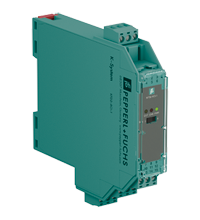
Solenoid Driver KFD2-RCI-1
- 1-channel signal conditioner
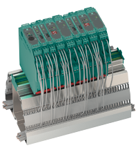
- 24 V DC supply (Power Rail)
- Output 20.4 mA at 13.5 V DC
- 19 V DC ... 30 V DC input
- Test pulse immunity
- Line fault detection (LFD)
- Up to SIL 3 acc. to IEC/EN 61508


Please note: All product-related documents, such as certificates, declarations of conformity, etc., which were issued prior to the conversion under the name Pepperl+Fuchs GmbH or Pepperl+Fuchs AG, also apply to Pepperl+Fuchs SE.
Download the complete datasheet as a PDF:
Datasheet excerpt: Technical data of KFD2-RCI-1
| General specifications | ||
|---|---|---|
| Signal type | Digital Output | |
| Functional safety related parameters | ||
| Safety Integrity Level (SIL) | SIL 3 | |
| Supply | ||
| Connection | Power Rail or terminals 14+, 15- | |
| Rated voltage | 19 ... 30 V DC | |
| Rated current | < 35 mA | |
| Power consumption | < 0.8 W | |
| Input | ||
| Connection side | control side | |
| Connection | terminals 10+, 11- | |
| Test pulse length | max. 2 ms from DO card | |
| Input current | 40 mA at 19 ... 30 V DC | |
| Signal level | 1-signal: 19 ... 30 V DC 0-signal: 0 ... 5 V DC |
|
| Power consumption | < 1.2 W | |
| Operating mode | loop powered | |
| Output | ||
| Connection side | field side/control side | |
| Connection | terminals 1+, 3- (terminals 1+, 2 for test loop) | |
| Internal resistor | approx. 275 Ω | |
| Current | ≤ 20.4 mA | |
| Voltage | ≥ 13.5 V | |
| Open loop voltage | > 16 V | |
| Voltage | 1-signal: > 13.5 V | |
| Current | 1-signal: 20.4 A 0-signal: 4.2 mA |
|
| Load | max. 650 Ω | |
| Response time | < 40 ms input to output | |
| Line fault detection | short circuit voltage < 1 V , open circuit voltage > 16 V | |
| Output II | ||
| Connection | terminal 7: source (-) or sink (+), terminal 8: source (+), terminal 9: sink (-) | |
| Current | 11 mA (source or sink mode) | |
| Voltage | 9 ... 30 V sink mode from external supply | |
| Load | max. 650 Ω , source mode , for HART ≥ 230 Ω | |
| Communication | pass-through of HART signal between input II and output | |
| Galvanic isolation | ||
| Field circuit/control circuit | basic insulation according to IEC 61010-1, rated insulation voltage 300 Veff | |
| Input/power supply | functional insulation, rated insulation voltage 50 Veff | |
| Output II/power supply | functional insulation, rated insulation voltage 50 Veff | |
| Indicators/settings | ||
| Display elements | LEDs | |
| Control elements | DIP switch | |
| Configuration | via DIP switches | |
| Labeling | space for labeling at the front | |
| Directive conformity | ||
| Electromagnetic compatibility | ||
| Directive 2014/30/EU | EN 61326-1:2013 (industrial locations) | |
| Conformity | ||
| Electromagnetic compatibility | NE 21:2012 | |
| Degree of protection | IEC 60529:2001 | |
| Ambient conditions | ||
| Ambient temperature | -20 ... 60 °C (-4 ... 140 °F) | |
| Mechanical specifications | ||
| Degree of protection | IP20 | |
| Connection | screw terminals | |
| Mass | approx. 150 g | |
| Dimensions | 20 x 119 x 115 mm (0.8 x 4.7 x 4.5 inch) (W x H x D) , housing type B2 | |
| Height | 119 mm | |
| Width | 20 mm | |
| Depth | 115 mm | |
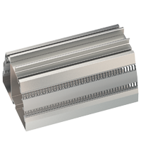
| Mounting | on 35 mm DIN mounting rail acc. to EN 60715:2001 | |
| General information | ||
| Supplementary information | Observe the certificates, declarations of conformity, instruction manuals, and manuals where applicable. For information see www.pepperl-fuchs.com. | |
Classifications
| System | Classcode |
|---|---|
| ECLASS 13.0 | 27210101 |
| ECLASS 12.0 | 27210190 |
| ECLASS 11.0 | 27210190 |
| ECLASS 10.0.1 | 27210190 |
| ECLASS 9.0 | 27210190 |
| ECLASS 8.0 | 27210190 |
| ECLASS 5.1 | 27210121 |
| ETIM 9.0 | EC001485 |
| ETIM 8.0 | EC001485 |
| ETIM 7.0 | EC001485 |
| ETIM 6.0 | EC001485 |
| ETIM 5.0 | EC001485 |
| UNSPSC 12.1 | 39121008 |
Details: KFD2-RCI-1
Function
This signal conditioner provides galvanic isolation between field circuits and control circuits.
The device can be used in emergency shutdown applications with HART positioners.
Via the logic input the positioner is energized or de-energized (emergency shutdown).
Independent of the status, a second input enables HART communication with the positioner. With this the asset management system can request for example diagnostic information or can initiate a partial stroke test.
The HART communication also works with de-energized positioner.
If the device is operated via Power Rail, additionally a collective error message is available.
Informative Literature: KFD2-RCI-1
| Literature | Language | File Type | File Size |
|---|---|---|---|
| Application Report - Biological Cleaning of Wastwater and Secondary Sedimentation Stage | ENG | 566 KB | |
| Application Report - Generating Electricity in Coal-Fired Power Plants | ENG | 412 KB | |
| Application Report - Sand Trap and Preliminary Sedimentation Stage | ENG | 448 KB | |
| Application Report - Screening Systems in Sewage Treatment Plants | ENG | 577 KB |
Product Documentation: KFD2-RCI-1
| Safety and Security Documentation | Language | File Type | File Size |
|---|---|---|---|
| Instruction manual | ENG | 41 KB | |
| Safety Manual | ENG | 597 KB | |
| Manuals | |||
| System Manual | ENG | 3694 KB | |
Design / Simulation: KFD2-RCI-1
| CAD | Language | File Type | File Size |
|---|---|---|---|
| CAD 3-D / CAD 3-D | ALL | STP | 3123 KB |
Approvals: KFD2-RCI-1
| Certificates | Certificate No. | Language | File Type | File Size |
|---|---|---|---|---|
| exida Functional Safety Assessment | P+F 0905-35R1-C R015 V1R0 | ALL | 599 KB | |
| Declaration of Conformity | ||||
| EU Declaration of Conformity (P+F) | TDOC-7214_ENG | ENG | 219 KB | |
| UK Declaration of Conformity (P+F) | TDOC-7231_ENG | ENG | 192 KB | |
Associated Products: KFD2-RCI-1
| Matching System Components | ||||||
|---|---|---|---|---|---|---|
|
||||||
|
||||||
|
||||||
|
||||||
|
||||||
|
||||||
| Accessories | ||||||
|
||||||
|
||||||


Choose from various selection criteria like safety integrity level, performance level, device function, and signal type and find the SIL/PL assessed device that you are looking for.


Pepperl+Fuchs SE
Lilienthalstraße 200
68307 Mannheim
Germany
info@de.pepperl-fuchs.com
 +49 621 776-0
Pepperl+Fuchs is a leading developer and manufacturer of electronic sensors and components for the global automation market. Continuous innovation, enduring quality, and steady growth have been the foundation of our success for more than 70 years. Pepperl+Fuchs employs 6,300 people worldwide and has manufacturing facilities in Germany, USA, Singapore, Hungary, Indonesia and Vietnam, most of them ISO 9001 certified.