

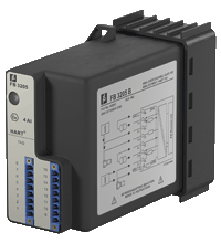
HART Transmitter Power Supply, Input Isolator FB3205B
- 4-channel
- Inputs Ex ia
- Installation in suitable enclosures in Zone 1
- Module can be exchanged under voltage (hot swap)
- Power supply for 2- or 3-wire transmitters with 4 mA ... 20 mA
- Supply circuit 15 V (20 mA)
- Input from active signals of 4-wire transmitters
- HART communication via field bus or service bus
- Simulation mode for service operations (forcing)
- Line fault detection (LFD)
- Permanently self-monitoring


Please note: All product-related documents, such as certificates, declarations of conformity, etc., which were issued prior to the conversion under the name Pepperl+Fuchs GmbH or Pepperl+Fuchs AG, also apply to Pepperl+Fuchs SE.
Download the complete datasheet as a PDF:
Datasheet excerpt: Technical data of FB3205B
| Supply | ||
|---|---|---|
| Connection | backplane bus | |
| Rated voltage | 12 V DC , only in connection with the power supplies FB92** | |
| Power consumption | 3 W | |
| Internal bus | ||
| Connection | backplane bus | |
| Interface | manufacturer-specific bus to standard com unit | |
| Input | ||
| Number of channels | 4 | |
| Suitable field devices | transmitters for pressure, differential pressure, level, flow, temperature, etc. | |
| Connection | 2-wire transmitter (HART): supply circuit: channel I 1+, 2-, channel II 5+, 6-, channel III 9+, 10-, channel IV 13+, 14- 3-wire transmitter: supply circuit: channel I 1+, 4-, channel II 5+, 8-, channel III 9+, 12-, channel IV 13+, 16- measuring circuit: channel I 3+, 4-, channel II 7+, 8-, channel III 11+, 12-, channel IV 15+, 16- 4-wire transmitter (separately powered): measuring circuit: channel I 3+, 4-, channel II 7+, 8-, channel III 11+, 12-, channel IV 15+, 16- |
|
| Input resistance | 15 Ω (channel I: 3, 4; channel II: 7, 8; channel III: 11, 12; channel IV: 15, 16) | |
| Line fault detection | can be switched on/off for each channel via configuration tool , configurable via configuration tool | |
| Short-circuit | Ex works settings: > 22 mA configurable between 0 ... 26 mA | |
| Open-circuit | Ex works settings: < 1 mA configurable between 0 ... 26 mA | |
| Transmitter supply voltage | min. 15 V at 20 mA | |
| Transfer characteristics | ||
| Deviation | ||
| After calibration | 0.1 % of the signal range at 20 °C (68 °F) | |
| Resolution | 12 Bit (0 ... 26 mA) | |
| Refresh time | 80 ms 130 ms during HART |
|
| Indicators/settings | ||
| LED indicator | LED green: supply , flashing: calibration error LED red: line fault , flashing: communication error |
|
| Directive conformity | ||
| Electromagnetic compatibility | ||
| Directive 2004/108/EC | EN 61326-1 | |
| Conformity | ||
| Electromagnetic compatibility | NE 21 | |
| Degree of protection | IEC 60529 | |
| Ambient conditions | ||
| Ambient temperature | -20 ... 60 °C (-4 ... 140 °F) | |
| Storage temperature | -25 ... 85 °C (-13 ... 185 °F) | |
| Relative humidity | 95 % non-condensing | |
| Shock resistance | shock type I, shock duration 11 ms, shock amplitude 50 m/s2, number of shock directions 6, number of shocks per direction 100 | |
| Vibration resistance | frequency range 5 ... 500 Hz, amplitude 5 ... 13.2 Hz ± 1.5 mm, 13.2 ... 100 Hz 1g, sweep rate 1 octave/min, duration 10 sweeps 5 Hz - 100 Hz - 5 Hz | |
| Damaging gas | designed for operation in environmental conditions acc. to ISA-S71.04-1985, severity level G3 | |
| Mechanical specifications | ||
| Degree of protection | IP20 (module) , a separate housing is required acc. to the system description | |
| Connection | removable front connector with screw flange (accessory) wiring connection via spring terminals (0.14 ... 1.5 mm2) or screw terminals (0.08 ... 1.5 mm2) |
|
| Mass | approx. 750 g | |
| Dimensions | 57 x 107 x 132 mm (2.2 x 4.2 x 5.2 inch) | |
| Data for application in connection with hazardous areas | ||
| EU-Type Examination Certificate | PTB 97 ATEX 1074 U | |
| Marking |  II 2(1) G Ex d [ia] IIC , [Ex iaD] II 2(1) G Ex d [ia] IIC , [Ex iaD] |
|
| Supply | ||
| Voltage | 28 V | |
| Current | 90 mA | |
| Power | 626 mW (linear characteristic) | |
| Input | ||
| Voltage | 0.7 V | |
| Current | 2.3 mA | |
| Power | 2 mW (trapezoid characteristic curve) | |
| Galvanic isolation | ||
| Input/power supply, internal bus | safe electrical isolation acc. to EN 60079-11, voltage peak value 375 V | |
| Directive conformity | ||
| Directive 94/9/EC | EN 60079-0, EN 60079-1, EN 60079-11, EN 60079-26, EN 61241-0, EN 61241-11 | |
| International approvals | ||
| IECEx approval | pending | |
Classifications
| System | Classcode |
|---|---|
| ECLASS 13.0 | 27210120 |
| ECLASS 12.0 | 27210101 |
| ECLASS 11.0 | 27210120 |
| ECLASS 10.0.1 | 27210120 |
| ECLASS 9.0 | 27210120 |
| ECLASS 8.0 | 27210120 |
| ECLASS 5.1 | 27210120 |
| ETIM 9.0 | EC001485 |
| ETIM 8.0 | EC001485 |
| ETIM 7.0 | EC001485 |
| ETIM 6.0 | EC001485 |
| ETIM 5.0 | EC001485 |
| UNSPSC 12.1 | 39121008 |
Details: FB3205B
Function
The transmitter power supply feeds 2- and 3-wire transmitters.
Active signals from separately powered field devices and 4-wire transmitters can be connected.
Open and short-circuit line faults are detected.
The intrinsically safe inputs are galvanically isolated from the bus and the power supply.
Product Documentation: FB3205B
| Safety and Security Documentation | Language | File Type | File Size |
|---|---|---|---|
| Instruction manual | ENG | 147 KB | |
| Manuals | |||
| FB Hardware Manual | ENG | 9157 KB | |
Approvals: FB3205B
| Certificates | Certificate No. | Language | File Type | File Size |
|---|---|---|---|---|
| Europe PTB ATEX Category 2 G | PTB 97 ATEX 1074U | ALL | 2619 KB |


Pepperl+Fuchs SE
Lilienthalstraße 200
68307 Mannheim
Germany
info@de.pepperl-fuchs.com
 +49 621 776-0
Pepperl+Fuchs is a leading developer and manufacturer of electronic sensors and components for the global automation market. Continuous innovation, enduring quality, and steady growth have been the foundation of our success for more than 70 years. Pepperl+Fuchs employs 6,300 people worldwide and has manufacturing facilities in Germany, USA, Singapore, Hungary, Indonesia and Vietnam, most of them ISO 9001 certified.