

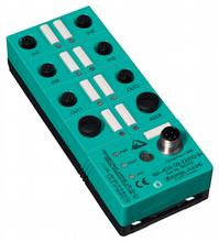
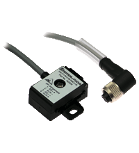
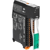
AS-Interface sensor/actuator module VBA-4E2A-G2-ZA/EA2-Ex
- Category, ignition protection class
[exsign] II 3G nA
[exsign] II 3D tD - A/B slave with extended addressing possibility for up to 62 slaves
- Addressing jack
- Flat cable connection with cable piercing technique, variable flat cable guide or M12 round connector for AS-Interface and external auxiliary power
- Communication monitoring
- Inputs for 2-, 3-, and 4-wire sensors
- Power supply of outputs from the external auxiliary voltage
- Supply for inputs from AS-Interface
- Function display for bus, ext. auxiliary voltage, inputs and outputs
- Detection of overload on sensor supply
- Detection of output overload


Please note: All product-related documents, such as certificates, declarations of conformity, etc., which were issued prior to the conversion under the name Pepperl+Fuchs GmbH or Pepperl+Fuchs AG, also apply to Pepperl+Fuchs SE.
Datasheet excerpt: Technical data of VBA-4E2A-G2-ZA/EA2-Ex
| Product Description |
|---|
| G2 flat module 4 inputs (PNP) and 2 electronic outputs |
| General specifications | ||
|---|---|---|
| Node type | A/B node | |
| AS-Interface specification | V3.0 | |
| Required master specification | ≥ V2.1 | |
| Group, category, type of protection |  II 3G EEx nA II T4 X II 3D Ex tD A22 IP67 T85°C X II 3G EEx nA II T4 X II 3D Ex tD A22 IP67 T85°C X |
|
| Indicators/operating means | ||
| LED FAULT | error display; LED red red: communication error or address is 0 red flashing: overload of sensor power supply or outputs |
|
| LED PWR | AS-Interface voltage; LED green | |
| LED AUX | ext. auxiliary voltage UAUX ; LED green | |
| LED IN | switching state (input); 4 LED yellow | |
| LED OUT | Switching state (output); 2 LED yellow | |
| Electrical specifications | ||
| Auxiliary voltage (output) | 20 ... 30 V DC PELV | |
| Rated operating voltage | 26.5 ... 31.6 V PELV from AS-Interface | |
| Rated operating current | ≤ 40 mA (without sensors) / max. 240 mA | |
| Protection class | III | |
| Surge protection | UAUX, Uin: Over voltage category III, safe isolated power supplies (PELV) | |
| Input | ||
| Number/Type | 4 inputs for 2- or 3-wire sensors (PNP), DC option 2 inputs for 4-wire sensors (PNP), DC |
|
| Supply | from AS-Interface | |
| Voltage | 21 ... 26 V | |
| Current loading capacity | ≤ 200 mA (TB ≤ 40 °C), ≤ 150 mA (TB ≤ 60 °C), overload-proof and short-circuit protected |
|
| Input current | ≤ 8 mA (limited internally) | |
| Switching point | according to DIN EN 61131-2 (Type 2) | |
| 0 (unattenuated) | ≤ 2 mA | |
| 1 (attenuated) | ≥ 4 mA | |
| Output | ||
| Number/Type | 2 electronic outputs, PNP, overload and short-circuit proof | |
| Supply | from external auxiliary voltage UAUX | |
| Current | 1 A per output, 2 A total | |
| Voltage | ≥ (UAUX - 0.5 V) | |
| Compliance with standards and directives | ||
| Directive conformity | observe notices on the certificate of conformity. | |
| EMC Directive 2004/108/EC | EN 50295:1999-10, EN 61326:2002-03 |
|
| ATEX Directive 94/9/EC | EN 60079-15:2003, IEC / EN 60947-5-2:2004 | |
| Standard conformity | ||
| AS-Interface | EN 50295:1999, IEC 62026-2:2006 | |
| Programming instructions | ||
| Profile | S-7.A.2 | |
| IO code | 7 | |
| ID code | A | |
| ID1 code | 7 | |
| ID2 code | 2 | |
| Data bits (function via AS-Interface) | ||
| D0 | ||
| D1 | ||
| D2 | ||
| D3 | ||
| Parameter bits (programmable via AS-i) | function | |
| P0 | not used | |
| P1 | not used | |
| P2 | not used | |
| P3 | not used | |
| Ambient conditions | ||
| Ambient temperature | -25 ... 60 °C (-13 ... 140 °F) | |
| Storage temperature | -25 ... 70 °C (-13 ... 158 °F) | |
| Mechanical specifications | ||
| Degree of protection | IP67 according to EN 60529 | |
| Connection | AS-Interface/UAUX: Cable piercing method yellow flat cable/black flat cable or M12 round connector Inputs/outputs: M12 round connector |
|
| Material | ||
| Housing | PBT | |
| Cable | ||
| Length | max. 30 m (Inputs) | |
| Mass | 150 g | |
| Equipment protection level Gc (nA) | ||
| Instruction | Manual electrical apparatus for hazardous areas |
|
| Device category 3G (nA) | for use in hazardous areas with gas, vapour and mist | |
| CE marking | [*PD-Z02586A*] | |
| ATEX marking | II 3G EEx nA II T4 X |
|
| Directive conformity | 94/9/EG | |
| Standards | EN 60079-15:2003 Ignition protection category "nA" |
|
| General | The apparatus has to be operated according to the appropriate data in the data sheet and in this instruction manual. The data stated in the data sheet are restricted by this operating instruction! The special conditions must be observed! |
|
| Installation, commissioning | Laws and/or regulations and standards governing the use or intended usage goal must be observed. | |
| Maintenance | No modifications must be undertaken on apparatus, which is operated in hazardous areas. Repairs to such apparatus are not permissible. | |
| Special conditions | ||
| Maximum permissible ambient temperature TUmax | Dependent on the sensor supply, the on-load current is as stated in the data sheet. | |
| Protection from mechanical danger | The apparatus must be protected from mechanical damage. | |
| Protection from UV light | The apparatus must be protected from damaging UV radiation. | |
| Equipment protection level Dc | ||
| Device category 3D | for use in hazardous areas with non-conducting combustible dust | |
| CE marking | [*PD-Z02586A*] | |
| ATEX marking | II 3D Ex tD A22 IP67 T85°C X |
|
| Directive conformity | 94/9/EG | |
| Standards | EN 61241-1:2004 Protection via housing "tD" |
|
| General | The apparatus has to be operated according to the appropriate data in the data sheet and in this instruction manual. The data stated in the data sheet are restricted by this operating instruction! The special conditions must be observed! |
|
| Installation, commissioning | Laws and/or regulations and standards governing the use or intended usage goal must be observed. | |
| Maintenance | No modifications must be undertaken on apparatus, which is operated in hazardous areas. Repairs to such apparatus are not permissible. | |
| Special conditions | ||
| Protection from mechanical danger | The apparatus must be protected from mechanical damage. | |
| Plug connector | Plug connectors must not be removed or plugged in under stress. Deposits of dust must be removed before unplugging a connector. When the plug connectors are disconnected, care must be taken to ensure that dirt does not get into the internal area (d. h. normally sealed by the connected plug connector). For the socket a VAZ-V1-B dummy plug must be used for this purpose (Pepperl+Fuchs mounting accessory). A VAZ-VIS-B cap (Pepperl+Fuchs mounting accessory) must be used to protect the plug. The tightening torque value for the plugs and caps is 0.4 Nm ... 0.5 Nm. Connectors should be tightened thoroughly by hand. In order to prevent unintentional loosening of the plug connector, the connector must be secured with the V1 Clip (Pepperl+Fuchs mounting accessory). The cables are to be laid in such a way that no tension is exerted on the connector. | |
| General information | ||
| Use in the hazardous area | see instruction manuals | |
| Category | 3G; 3D | |
Classifications
| System | Classcode |
|---|---|
| ECLASS 13.0 | 27242604 |
| ECLASS 12.0 | 27242604 |
| ECLASS 11.0 | 27242604 |
| ECLASS 10.0.1 | 27242604 |
| ECLASS 9.0 | 27242604 |
| ECLASS 8.0 | 27242604 |
| ECLASS 5.1 | 27242604 |
| ETIM 9.0 | EC001599 |
| ETIM 8.0 | EC001599 |
| ETIM 7.0 | EC001599 |
| ETIM 6.0 | EC001599 |
| ETIM 5.0 | EC001599 |
| UNSPSC 12.1 | 39121535 |
Details: VBA-4E2A-G2-ZA/EA2-Ex
Datasheet: VBA-4E2A-G2-ZA/EA2-Ex
| Datasheet | File Type | File Size |
|---|---|---|
| Datasheet VBA-4E2A-G2-ZA/EA2-Ex | 321 KB | |
| Fiche de données VBA-4E2A-G2-ZA/EA2-Ex | 392 KB | |
| Datenblatt VBA-4E2A-G2-ZA/EA2-Ex | 320 KB |
Documents: VBA-4E2A-G2-ZA/EA2-Ex
| Instruction leaflets | File Type | File Size |
|---|---|---|
| Instruction leaflet / Beipackzettel | 3478 KB |
CAD+CAE: VBA-4E2A-G2-ZA/EA2-Ex
| CAD | File Type | File Size |
|---|---|---|
| CAD 3-D / CAD 3-D | STP | 236 KB |
Associated Products: VBA-4E2A-G2-ZA/EA2-Ex
| Matching System Components | ||||||
|---|---|---|---|---|---|---|
|
||||||
| Accessories | ||||||
|
||||||
|
||||||
|
||||||
|
||||||
|
||||||
|
||||||
|
||||||


This free PDF white paper compares the different TCP-based communication protocols (AMQP, OPC UA, MQTT, REST API) that have found their way up and are considered the enablers of IIoT and Industry 4.0. Get your free download now!
AS-Interface Switch Cabinet Module KE5 – Simple Handling and Improved Manageability
The unique housing design of the new KE5 switch cabinet module enables distinct visibility and simplifies mounting, wiring, and maintenance inside switch cabinets and junction boxes.


Pepperl+Fuchs SE
Lilienthalstraße 200
68307 Mannheim
Germany
info@de.pepperl-fuchs.com
 +49 621 776-0
Pepperl+Fuchs is a leading developer and manufacturer of electronic sensors and components for the global automation market. Continuous innovation, enduring quality, and steady growth have been the foundation of our success for more than 70 years. Pepperl+Fuchs employs 6,300 people worldwide and has manufacturing facilities in Germany, USA, Singapore, Hungary, Indonesia and Vietnam, most of them ISO 9001 certified.