

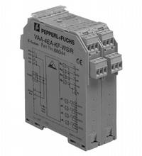
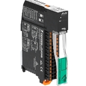
AS-Interface sensor/actuator module VAA-4EA-KF-WS/R
- Housing with removable, coded terminals
- AS-Interface connection via Power Rail
- Communication monitoring, turn-off
- Outputs loadable up to 8 A (per module)
- Inputs for 110 V AC sensors
- Addressing jack
- External power supply of sensors
- Function display for bus, inputs and outputs
- 4 potential-free switch-contacts


Please note: All product-related documents, such as certificates, declarations of conformity, etc., which were issued prior to the conversion under the name Pepperl+Fuchs GmbH or Pepperl+Fuchs AG, also apply to Pepperl+Fuchs SE.
Datasheet excerpt: Technical data of VAA-4EA-KF-WS/R
| Product Description |
|---|
| Cabinet module 4 inputs (sensor for alternating voltage) and 4 relay outputs |
| General specifications | ||
|---|---|---|
| Node type | Standard node | |
| UL File Number | E87056 | |
| Indicators/operating means | ||
| LED PWR/FAULT | dual-LED green/red green: AS-Interface voltage, normal operation red: communication error or address 0 |
|
| LED IN | switching state (input); 4 LED yellow | |
| LED OUT | Switching state (output); 4 LED yellow | |
| Electrical specifications | ||
| Rated operating voltage | 26.5 ... 31.6 V from AS-Interface | |
| Rated operating current | ≤ 100 mA | |
| Input | ||
| Number/Type | 4 sensors, V AC | |
| Supply | external AC 110 V | |
| Switching point | ||
| 0 (unattenuated) | ≤ 2 mA | |
| 1 (attenuated) | ≥ 20 mA | |
| Output | ||
| Number/Type | 4 relay outputs | |
| Galvanic isolation | AS-Interface - Outputs: Safe isolation according to EN 50178 (250 V AC) Output - Output: Safe isolation according to EN 50178 (250 V AC) |
|
| Contact loading | 2 A/30 V DC per output 2 A/250 V AC per output |
|
| Life span | mechanical: 30 x 106 switching cycles electrical: 1 x 10⁶ operations (30 V DC, 2 A, ohmic) 5 x 10⁶ operations (250 V AC, 2 A, cosφ = 1) 4.5 x 10⁶ switching cycles (250 V AC, 2 A, cosφ = 0.7) |
|
| Programming instructions | ||
| Profile | S-7.F | |
| IO code | 7 | |
| ID code | F | |
| Data bits (function via AS-Interface) | ||
| D0 | ||
| D1 | ||
| D2 | ||
| D3 | ||
| Parameter bits (programmable via AS-i) | function | |
| P0 | communication monitoring P0 = 1 (default settings), monitoring = ON, i.e. if communication fails, the outputs are de-energised P0 = 0, monitoring = OFF, if communication fails, the outputs maintain their condition |
|
| P1 | not used | |
| P2 | not used | |
| P3 | not used | |
| Ambient conditions | ||
| Ambient temperature | -25 ... 70 °C (-13 ... 158 °F) | |
| Storage temperature | -25 ... 85 °C (-13 ... 185 °F) | |
| Mechanical specifications | ||
| Degree of protection | IP20 according to EN 60529 | |
| Connection | removable coded terminals, Power Rail | |
| Mass | 170 g | |
| Mounting | DIN mounting rail | |
Classifications
| System | Classcode |
|---|---|
| ECLASS 13.0 | 27242604 |
| ECLASS 12.0 | 27242604 |
| ECLASS 11.0 | 27242604 |
| ECLASS 10.0.1 | 27242604 |
| ECLASS 9.0 | 27242604 |
| ECLASS 8.0 | 27242604 |
| ECLASS 5.1 | 27242604 |
| ETIM 9.0 | EC001599 |
| ETIM 8.0 | EC001599 |
| ETIM 7.0 | EC001599 |
| ETIM 6.0 | EC001599 |
| ETIM 5.0 | EC001599 |
| UNSPSC 12.1 | 39121535 |
Details: VAA-4EA-KF-WS/R
Datasheet: VAA-4EA-KF-WS/R
| Datasheet | File Type | File Size |
|---|---|---|
| Datasheet VAA-4EA-KF-WS/R | 288 KB | |
| Fiche de données VAA-4EA-KF-WS/R | 305 KB | |
| Datenblatt VAA-4EA-KF-WS/R | 212 KB |
Documents: VAA-4EA-KF-WS/R
| Instruction leaflets | File Type | File Size |
|---|---|---|
| Instruction leaflet / Beipackzettel | 236 KB |
CAD+CAE: VAA-4EA-KF-WS/R
| CAD | File Type | File Size |
|---|---|---|
| CAD 3-D / CAD 3-D | STP | 289 KB |
Approvals+Certificates: VAA-4EA-KF-WS/R
| Certificates | File Type | File Size |
|---|---|---|
| US CA UL | LINK | --- |
Associated Products: VAA-4EA-KF-WS/R
| Accessories | ||||||
|---|---|---|---|---|---|---|
|
||||||
|
||||||

This free PDF white paper compares the different TCP-based communication protocols (AMQP, OPC UA, MQTT, REST API) that have found their way up and are considered the enablers of IIoT and Industry 4.0. Get your free download now!
AS-Interface Switch Cabinet Module KE5 – Simple Handling and Improved Manageability
The unique housing design of the new KE5 switch cabinet module enables distinct visibility and simplifies mounting, wiring, and maintenance inside switch cabinets and junction boxes.


Pepperl+Fuchs SE
Lilienthalstraße 200
68307 Mannheim
Germany
info@de.pepperl-fuchs.com
 +49 621 776-0
Pepperl+Fuchs is a leading developer and manufacturer of electronic sensors and components for the global automation market. Continuous innovation, enduring quality, and steady growth have been the foundation of our success for more than 70 years. Pepperl+Fuchs employs 6,300 people worldwide and has manufacturing facilities in Germany, USA, Singapore, Hungary, Indonesia and Vietnam, most of them ISO 9001 certified.