

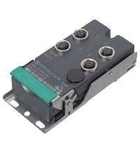
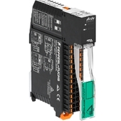
AS-Interface actuator module VAA-4A-G12-EA2L
- One-piece housing with stainless steel base
- Installation without tools
- Metal threaded inserts with SPEEDCON technology
- Flat cable connection with cable piercing technique, variable flat cable guide
- Red LED per channel, lights up in the event of output overload
- Communication monitoring, configurable
- DIN rail mounting
- AS-Interface certificate


Please note: All product-related documents, such as certificates, declarations of conformity, etc., which were issued prior to the conversion under the name Pepperl+Fuchs GmbH or Pepperl+Fuchs AG, also apply to Pepperl+Fuchs SE.
Download the complete datasheet as a PDF:
Datasheet excerpt: Technical data of VAA-4A-G12-EA2L
| Product Description |
|---|
| G12 compact module, 4 outputs (PNP) |
| General specifications | ||
|---|---|---|
| Node type | Standard node | |
| AS-Interface specification | V3.0 | |
| Required gateway specification | ≥ V2.1 | |
| Profile | S-8.1 | |
| IO code | 8 | |
| ID code | 1 | |
| ID1 code | F | |
| ID2 code | E | |
| UL File Number | E223772 | |
| Indicators/operating means | ||
| LED FAULT | error display; LED red red: communication error or address is 0 red flashing: Output supply overload |
|
| LED PWR | AS-Interface voltage; green LED green: voltage OK flashing green: address 0 |
|
| LED AUX | ext. auxiliary voltage UAUX; dual LED green/red green: voltage OK red: reverse voltage |
|
| LED OUT | Switching status (output); 4 yellow/red LEDs Yellow: output active Red: output overload |
|
| Electrical specifications | ||
| Auxiliary voltage (output) | 24 V DC ± 15 % PELV | |
| Rated operating voltage | 26.5 ... 31.6 V from AS-Interface | |
| Rated operating current | ≤ 40 mA | |
| Protection class | III | |
| Surge protection | UAUX, Uin: Over voltage category III, safe isolated power supplies (PELV) derived from mains up to 300 V AC line-to-neutral | |
| Output | ||
| Number/Type | 4 electronic outputs, PNP | |
| Supply | from external auxiliary voltage UAUX | |
| Voltage | ≥ (UAUX - 0.5 V) | |
| Current | 2 A per output 6 A total (TB ≤ 40 °C) 4 A total (TB ≤ 70 °C) |
|
| Directive conformity | ||
| Electromagnetic compatibility | ||
| Directive 2014/30/EU | EN 62026-2:2013 EN 61000-6-2:2005 EN 61000-6-4:2007 | |
| Standard conformity | ||
| Degree of protection | EN 60529:2000 | |
| Fieldbus standard | EN 62026-2:2013 | |
| Emitted interference | EN 61000-6-4:2007 | |
| AS-Interface | EN 62026-2:2013 | |
| Noise immunity | EN 61000-6-2:2005 | |
| Ambient conditions | ||
| Ambient temperature | -25 ... 70 °C (-13 ... 158 °F) | |
| Storage temperature | -25 ... 85 °C (-13 ... 185 °F) | |
| Relative humidity | 85 % , noncondensing | |
| Altitude | ≤ 2000 m above MSL | |
| Shock and impact resistance | 30 g, 11 ms in 6 spatial directions 3 shocks 10 g, 16 ms in 6 spatial directions 1000 shocks |
|
| Vibration resistance | 0.75 mm 10 ... 57 Hz , 5 g 57 ... 150 Hz, 20 cycles | |
| Pollution degree | 3 | |
| Mechanical specifications | ||
| Degree of protection | IP67 | |
| Connection | Cable piercing method flat cable yellow/flat cable black inputs/outputs: M12 round connector |
|
| Material | ||
| Housing | PBT | |
| Mass | 200 g | |
| Tightening torque, cable gland | 0.4 Nm | |
| Dimensions | ||
| Height | 35 mm | |
| Width | 57.4 mm | |
| Length | 118 mm | |
| Mounting | Mounting plate | |
Classifications
| System | Classcode |
|---|---|
| ECLASS 13.0 | 27242604 |
| ECLASS 12.0 | 27242604 |
| ECLASS 11.0 | 27242604 |
| ECLASS 10.0.1 | 27242604 |
| ECLASS 9.0 | 27242604 |
| ECLASS 8.0 | 27242604 |
| ECLASS 5.1 | 27242604 |
| ETIM 9.0 | EC001599 |
| ETIM 8.0 | EC001599 |
| ETIM 7.0 | EC001599 |
| ETIM 6.0 | EC001599 |
| ETIM 5.0 | EC001599 |
| UNSPSC 12.1 | 39121535 |
Details: VAA-4A-G12-EA2L
Function
The VAA-4A-G12-EA2L is an AS-Interface trigger module with 4 outputs. The outputs are electronic outputs which can be energized with max. 24 V DC and 2 A per output.
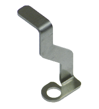
The solid housing permits fast mounting without tools, as well as easy removal without tools. The stainless steel shell and the cast housing ensure durability and a high type of protection.
The connection to the AS-Interface cable and to the external power supply is achieved via penetration technology in the integrated flat cable. The insert for the flat cables can be turned in 2 orientations.
All connections to the outputs are implemented via metal inserts for high stability. The connection to the actuators is achieved via an M12 x 1 circular connector with SPEEDCON quick locking option.
The supply of the outputs and the connected actuators is achieved via an external current source (AUX).
To indicate the current switching state, there is a LED for each channel fitted onto the top of the module. The outputs are protected against overload and short circuit, an output overload is indicated via one LED per channel.
A LED is available to indicate the AS-Interface voltage and that the module has an address 0. Another LED indicates errors in the AS-Interface communication, as well as periphery faults. A separate LED indicates the external power supply (AUX).
This module can be mounted in any position with 3 screws, or snapped onto the DIN rail, using the stainless steel holder.
An output overload is reported to the AS-Interface gateway via the function "periphery fault". The communication with the AS-Interface remains intact.
Product Documentation: VAA-4A-G12-EA2L
| Product information | Language | File Type | File Size |
|---|---|---|---|
| Label form / Beschriftungsformular | ALL | 304 KB | |
| Brief Instructions | |||
| Instruction leaflet / Beipackzettel | ALL | 558 KB | |
| Mounting Instruction G12 Modules | ENG | 176 KB | |
Design / Simulation: VAA-4A-G12-EA2L
| CAD | Language | File Type | File Size |
|---|---|---|---|
| CAD 3-D / CAD 3-D | ALL | STP | 4618 KB |
| CAD Portal / CAD Portal | ALL | LINK | --- |
| CAE | |||
| CAE EPLAN Data Portal / CAE EPLAN Data Portal | ALL | LINK | --- |
| CAE EPLAN macro EDZ / CAE EPLAN Makro EDZ | ALL | EDZ | 41 KB |
Approvals: VAA-4A-G12-EA2L
| Certificates | Certificate No. | Language | File Type | File Size |
|---|---|---|---|---|
| US CA UL | E223772 | ALL | LINK | --- |
| Worldwide AS-International Association AS-Interface | 78101 | ALL | 592 KB | |
| Declaration of Conformity | ||||
| EU Declaration of Conformity (P+F) / EU-Konformitäterklärung (P+F) | DOC-0978D | ALL | 118 KB | |
Associated Products: VAA-4A-G12-EA2L
| Accessories | ||||||
|---|---|---|---|---|---|---|
|
||||||
|
||||||
|
||||||
|
||||||


This free PDF white paper compares the different TCP-based communication protocols (AMQP, OPC UA, MQTT, REST API) that have found their way up and are considered the enablers of IIoT and Industry 4.0. Get your free download now!
AS-Interface Switch Cabinet Module KE5 – Simple Handling and Improved Manageability
The unique housing design of the new KE5 switch cabinet module enables distinct visibility and simplifies mounting, wiring, and maintenance inside switch cabinets and junction boxes.


Pepperl+Fuchs SE
Lilienthalstraße 200
68307 Mannheim
Germany
info@de.pepperl-fuchs.com
 +49 621 776-0
Pepperl+Fuchs is a leading developer and manufacturer of electronic sensors and components for the global automation market. Continuous innovation, enduring quality, and steady growth have been the foundation of our success for more than 70 years. Pepperl+Fuchs employs 6,300 people worldwide and has manufacturing facilities in Germany, USA, Singapore, Hungary, Indonesia and Vietnam, most of them ISO 9001 certified.