

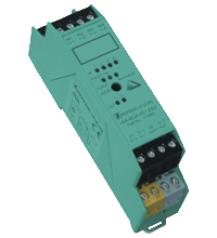
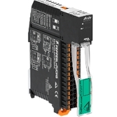
AS-Interface sensor/actuator module VBA-4E2A-KE1-Z/E2
- A/B node with extended addressing possibility for up to 62 nodes
- Housing with removable terminals
- Communication monitoring
- Inputs for 2-wire sensors and mechanical contacts
- Addressing jack
- Power supply of outputs from the external auxiliary voltage
- Power supply of inputs from the module
- Function display for bus, ext. auxiliary voltage, inputs and outputs


Please note: All product-related documents, such as certificates, declarations of conformity, etc., which were issued prior to the conversion under the name Pepperl+Fuchs GmbH or Pepperl+Fuchs AG, also apply to Pepperl+Fuchs SE.
Download the complete datasheet as a PDF:
Datasheet excerpt: Technical data of VBA-4E2A-KE1-Z/E2
| Product Description |
|---|
| KE1 switch cabinet module 4 inputs and 2 outputs |
| General specifications | ||
|---|---|---|
| Node type | A/B node | |
| AS-Interface specification | V2.1 | |
| Required gateway specification | ≥ V2.1 | |
| Profile | S-7.A.0 | |
| IO code | 7 | |
| ID code | A | |
| ID1 code | 7 | |
| ID2 code | 0 | |
| UL File Number | E223772 | |
| Indicators/operating means | ||
| LED FAULT | error display; LED red red: communication error or address is 0 red flashing: overload of outputs |
|
| LED PWR | AS-Interface voltage; LED green | |
| LED AUX | ext. auxiliary voltage UAUX ; LED green | |
| LED IN | switching state (input); 4 LED yellow | |
| LED OUT | Switching state (output); 2 LED yellow | |
| Electrical specifications | ||
| Auxiliary voltage (output) | 20 ... 30 V DC PELV | |
| Rated operating voltage | 26.5 ... 31.6 V from AS-Interface | |
| Rated operating current | ≤ 25 mA (without sensors) / max. 60 mA | |
| Protection class | III | |
| Surge protection | UAUX, Uin: Over voltage category III, safe isolated power supplies (PELV) | |
| Input | ||
| Number/Type | 4 inputs for 2-wire sensors (PNP), DC or for mechanical contacts | |
| Supply | from AS-Interface | |
| Input current | ≤ 8 mA (limited internally) | |
| Switching point | according to DIN EN 61131-2 (Type 2) | |
| 0 (unattenuated) | ≤ 2 mA | |
| 1 (attenuated) | ≥ 4 mA | |
| Signal delay | < 2 ms (input/AS-Interface) | |
| Signal frequency | ≤ 250 Hz | |
| Output | ||
| Number/Type | 2 electronic outputs, PNP, overload and short-circuit proof | |
| Supply | from external auxiliary voltage UAUX | |
| Voltage | ≥ (UAUX - 0.5 V) | |
| Current | O1/O2 max. 1.5 A, total 3 A (TB ≤ 40 °C) O1/O2 max. 1 A, total 2 A (TB ≤ 70 °C) |
|
| Usage category | DC-13 | |
| Directive conformity | ||
| Electromagnetic compatibility | ||
| Directive 2014/30/EU | EN 62026-2:2013 EN 61000-6-2:2001 EN 61000-6-4:2001 | |
| Standard conformity | ||
| Degree of protection | EN 60529:2000 | |
| Input | EN 61131-2:2007 | |
| Emitted interference | EN 61000-6-4:2001 | |
| AS-Interface | EN 62026-2:2013 | |
| Noise immunity | EN 61000-6-2:2001 | |
| Ambient conditions | ||
| Ambient temperature | -25 ... 70 °C (-13 ... 158 °F) | |
| Storage temperature | -25 ... 85 °C (-13 ... 185 °F) | |
| Relative humidity | 90 % , noncondensing | |
| Pollution degree | 2 | |
| Mechanical specifications | ||
| Degree of protection | IP20 | |
| Connection | removable terminals rated connection capacity: rigid/flexible (with and without wire-end ferrules): 0.25 mm2 ... 2.5 mm2 for multiple-wire connection with two wires of equal cross-section: flexible with twin wire-end ferrules: 0.5 mm2 ... 1.5 mm2 |
|
| Material | ||
| Housing | PA 66-FR | |
| Mass | 80 g | |
| Dimensions | ||
| Height | 48.5 mm | |
| Width | 22.5 mm | |
| Length | 99.6 mm | |
| Mounting | DIN mounting rail | |
Classifications
| System | Classcode |
|---|---|
| ECLASS 13.0 | 27242604 |
| ECLASS 12.0 | 27242604 |
| ECLASS 11.0 | 27242604 |
| ECLASS 10.0.1 | 27242604 |
| ECLASS 9.0 | 27242604 |
| ECLASS 8.0 | 27242604 |
| ECLASS 5.1 | 27242604 |
| ETIM 9.0 | EC001599 |
| ETIM 8.0 | EC001599 |
| ETIM 7.0 | EC001599 |
| ETIM 6.0 | EC001599 |
| ETIM 5.0 | EC001599 |
| UNSPSC 12.1 | 39121535 |
Details: VBA-4E2A-KE1-Z/E2
Function
The VBA-4E2A-KE1-Z/E2 AS-interface coupling module is a cabinet module with 4 inputs and 2 electronic outputs. The housing, only 22.5 mm in width and 48.5 mm in height, takes up little place in the switch cabinet. The module is mounted by snapping onto the 35 mm DIN rail in accordance with EN 50022.
Plug-in terminals are used for connection. 4-way terminal blocks (black) are used for the inputs. The connection of the outputs and the external auxiliary supply and AS-Interface is made through the 2-way terminal blocks (outputs black, auxiliary voltage gray and AS-Interface yellow). This makes it possible to separate individual actuators or to supply power during commissioning or servicing.
The supply of the inputs and the connected sensors occurs internally via the module (from AS-Interface). An LED on the front control plate is used to display the current switching state for each input and output.
Note:
The device is equipped with a watchdog, which switches the outputs to their de-energized state, when on the AS-interface cable is no communication for more than 40 ms.
An overload of the outputs is reported by the 'periphery error' to the AS-Interface master. Communication over the AS-Interface remains in effect.
Design / Simulation: VBA-4E2A-KE1-Z/E2
| CAD | Language | File Type | File Size |
|---|---|---|---|
| CAD 3-D / CAD 3-D | ALL | STP | 317 KB |
| CAD Portal / CAD Portal | ALL | LINK | --- |
| CAE | |||
| CAE EPLAN Data Portal / CAE EPLAN Data Portal | ALL | LINK | --- |
| CAE EPLAN macro EDZ / CAE EPLAN Makro EDZ | ALL | EDZ | 671 KB |
Approvals: VBA-4E2A-KE1-Z/E2
| Certificates | Certificate No. | Language | File Type | File Size |
|---|---|---|---|---|
| AS-Interface | 42001 | ALL | 80 KB | |
| US CA UL | CoC E223772 RptRef E223772-20220705 | ALL | 441 KB | |
| Worldwide AS-International Association AS-Interface | 42001 | ALL | 598 KB | |
| Declaration of Conformity | ||||
| EU Declaration of Conformity (P+F) / EU-Konformitäterklärung (P+F) | DOC-1011C | ALL | 115 KB | |
Associated Products: VBA-4E2A-KE1-Z/E2
| Accessories | ||||||
|---|---|---|---|---|---|---|
|
||||||
|
||||||
|
||||||


This free PDF white paper compares the different TCP-based communication protocols (AMQP, OPC UA, MQTT, REST API) that have found their way up and are considered the enablers of IIoT and Industry 4.0. Get your free download now!
AS-Interface Switch Cabinet Module KE5 – Simple Handling and Improved Manageability
The unique housing design of the new KE5 switch cabinet module enables distinct visibility and simplifies mounting, wiring, and maintenance inside switch cabinets and junction boxes.


Pepperl+Fuchs SE
Lilienthalstraße 200
68307 Mannheim
Germany
info@de.pepperl-fuchs.com
 +49 621 776-0
Pepperl+Fuchs is a leading developer and manufacturer of electronic sensors and components for the global automation market. Continuous innovation, enduring quality, and steady growth have been the foundation of our success for more than 70 years. Pepperl+Fuchs employs 6,300 people worldwide and has manufacturing facilities in Germany, USA, Singapore, Hungary, Indonesia and Vietnam, most of them ISO 9001 certified.