

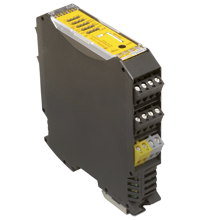
AS-Interface safety module VBA-8E8A8A-KE4-ZEL/E2L/SEL
- Compact solution providing a large number of safe outputs
- Functional switching of the safe outputs possible with standard outputs
- 1 A/B diagnostic slave possible per safe output
- 8 standard inputs for EDM
- Up to SIL3 (EN 62061) and PLe (EN13849-1)


Please note: All product-related documents, such as certificates, declarations of conformity, etc., which were issued prior to the conversion under the name Pepperl+Fuchs GmbH or Pepperl+Fuchs AG, also apply to Pepperl+Fuchs SE.
Download the complete datasheet as a PDF:
Datasheet excerpt: Technical data of VBA-8E8A8A-KE4-ZEL/E2L/SEL
| Product Description |
|---|
| KE4 switch cabinet module 8 safety-related electronic outputs, each switchable with a standard output, 8 standard inputs |
| General specifications | ||
|---|---|---|
| Node type | A/B slave, 2 standard slaves for inputs/outputs, additional slaves can be configured | |
| AS-Interface specification | V3.0 | |
| Required gateway specification | ≥ V3.0 | |
| Indicators/operating means | ||
| LED FAULT | error display; LED red red: communication error |
|
| LED AS-i | AS-Interface voltage; LED green | |
| LED AUX | ext. auxiliary voltage UAUX ; LED green | |
| LED IN | switching state (input); 8 LED yellow | |
| LED OUT | Switching state (output); 8 LED yellow | |
| LED ALARM | Alarm signal from the control; yellow LED | |
| Electrical specifications | ||
| Auxiliary voltage (input) | 24 V (20 VDC ... 30 VDC) PELV Max. current consumption: 8 A |
|
| Rated operating voltage | 18,0 ... 31.6 V from AS-Interface | |
| Rated operating current | < 200 mA | |
| Interface 1 | ||
| Interface type | Chip card slot | |
| Input | ||
| Number/Type | 8 digital inputs | |
| Supply | from external auxiliary voltage UAUX | |
| Voltage | 24 V DC | |
| Switching threshold | U < 5 V (low) U > 15 V (high) |
|
| Output | ||
| Number/Type | 8 safe electronic outputs 1 - 8 release circuits |
|
| Supply | from external auxiliary voltage UAUX | |
| Current loading capacity | 2 A per output, 8 A total note derating |
|
| Directive conformity | ||
| Electromagnetic compatibility | ||
| Directive 2014/30/EU | EN 62026-2:2013 | |
| Machinery Directive | ||
| Directive 2006/42/EC | EN 13849-1:2008/AC:2009 | |
| Standard conformity | ||
| Degree of protection | EN 60529:2000 | |
| Electrical safety | EN 13849-1:2008/AC:2009 | |
| Climatic conditions | EN 61131-2:2007 | |
| AS-Interface | EN 62026-2:2013 | |
| Functional safety | EN 61508:2010 EN 62061:2005/A1:2013 |
|
| Programming instructions | ||
| Profile | Diagnostic node: S-7.A.E, ID1 = 5 Input/output slave: S-7.F.E, ID1 = F Configuration slave: S-7.A.5, ID1 = 7 |
|
| Ambient conditions | ||
| Ambient temperature | 0 ... 55 °C (32 ... 131 °F) | |
| Storage temperature | -25 ... 85 °C (-13 ... 185 °F) | |
| Altitude | 0 ... 2000 m | |
| Mechanical specifications | ||
| Degree of protection | IP20 | |
| Connection | removable terminals rated connection capacity: rigid/flexible (with and without wire-end ferrules): 0.25 mm2 ... 2.5 mm2 for multiple-wire connection with two wires of equal cross-section: flexible with twin wire-end ferrules: 0.5 mm2 ... 1.5 mm2 |
|
| Material | ||
| Housing | PA 66-FR | |
| Mass | 270 g | |
| Dimensions | ||
| Height | 99 mm | |
| Width | 22.5 mm | |
| Length | 113 mm | |
| Mounting | DIN mounting rail | |
Classifications
| System | Classcode |
|---|---|
| ECLASS 13.0 | 27272603 |
| ECLASS 12.0 | 27242604 |
| ECLASS 11.0 | 27242604 |
| ECLASS 10.0.1 | 27242604 |
| ECLASS 9.0 | 27242604 |
| ECLASS 8.0 | 27242604 |
| ECLASS 5.1 | 27242604 |
| ETIM 9.0 | EC001599 |
| ETIM 8.0 | EC001599 |
| ETIM 7.0 | EC001599 |
| ETIM 6.0 | EC001599 |
| ETIM 5.0 | EC001599 |
| UNSPSC 12.1 | 39121535 |
Details: VBA-8E8A8A-KE4-ZEL/E2L/SEL
Function
The AS-Interface safety output module VBA-8E8A8A-KE4-ZEL/E2L/SEL is a switch cabinet module with eight safe electronic outputs. In addition, the module has eight inputs and one standard output per safe output. The safety output module allows safe switching processes to take place remotely in the box. The parallel wiring of safe actuators in the box is a thing of the past.
The housing is only 22.5 mm wide and takes up little space in the switch cabinet. A snapon function mounts the module onto the 35 mm mounting strip in line with EN 50022. An addressing socket for programming the basic address is integrated in the module. All further addresses can be configured via a configuration software.
The connection is made via plug-in terminals. Four-way (black) terminal blocks are used for the inputs. The AS-Interface is connected via a two-way terminal block (yellow). This allows the sensors or the power supply to be easily disconnected for commissioning or service. Power is supplied to the inputs by an external auxiliary power supply. Yellow LEDs display the current switching status of the inputs and outputs. Yellow LEDs display communication errors. A green LED displays the operating voltage and the 0 address.
Product Documentation: VBA-8E8A8A-KE4-ZEL/E2L/SEL
| Brief Instructions | Language | File Type | File Size |
|---|---|---|---|
| Mounting Instruction VBA-8E8A8A-KE4-ZEL/E2L/SE / Montageanleitung VBA-8E8A8A-KE4-ZEL/E2L/SE | ALL | 2066 KB | |
| Safety and Security Documentation | |||
| Instruction manual VBA-8E8A8A-KE4-ZEL/E2L/SE | ENG | 348 KB | |
Approvals: VBA-8E8A8A-KE4-ZEL/E2L/SEL
| Certificates | Certificate No. | Language | File Type | File Size |
|---|---|---|---|---|
| EU TUV Nord Functional Safety | 44 205 16000802 | ALL | 1457 KB | |
| Declaration of Conformity | ||||
| EU Declaration of Conformity (P+F) / EU-Konformitäterklärung (P+F) | DOC-2502E | ALL | 214 KB | |
Associated Products: VBA-8E8A8A-KE4-ZEL/E2L/SEL
| Accessories | ||||||
|---|---|---|---|---|---|---|
|
||||||
|
||||||
|
||||||
|
||||||


Pepperl+Fuchs SE
Lilienthalstraße 200
68307 Mannheim
Germany
info@de.pepperl-fuchs.com
 +49 621 776-0
Pepperl+Fuchs is a leading developer and manufacturer of electronic sensors and components for the global automation market. Continuous innovation, enduring quality, and steady growth have been the foundation of our success for more than 70 years. Pepperl+Fuchs employs 6,300 people worldwide and has manufacturing facilities in Germany, USA, Singapore, Hungary, Indonesia and Vietnam, most of them ISO 9001 certified.