

Not available for purchase
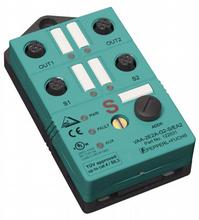
AS-Interface safety module VAA-2E2A-G2-S/EA2
- Addressing jack
- Flat cable connection with cable piercing technique, variable flat cable guide
- Communication monitoring
- Power supply of outputs from the external auxiliary voltage
- 2 safe inputs for mechanical contacts such as EMERGENCY-STOP switch
- Power supply of inputs from the module
- Function display for bus, ext. auxiliary voltage, inputs and outputs
- Output overload monitoring
- Switchable internal logic operation of the inputs and outputs via parameter bit


Please note: All product-related documents, such as certificates, declarations of conformity, etc., which were issued prior to the conversion under the name Pepperl+Fuchs GmbH or Pepperl+Fuchs AG, also apply to Pepperl+Fuchs SE.
Download the complete datasheet as a PDF:
Datasheet excerpt: Technical data of VAA-2E2A-G2-S/EA2
| Product Description |
|---|
| G2 safety module 2 safety-related inputs and 2 conventional electronic outputs |
| General specifications | ||
|---|---|---|
| Node type | Safety-Slave | |
| AS-Interface specification | V2.1 | |
| Required master specification | ≥ V2.1 | |
| UL File Number | E87056 | |
| Functional safety related parameters | ||
| Safety Integrity Level (SIL) | SIL 3 | |
| MTTFd | 200 a | |
| Indicators/operating means | ||
| LED FAULT | error display; LED red red: communication error or address is 0 red flashing: Output supply overload |
|
| LED PWR | AS-Interface voltage; LED green | |
| LED AUX | ext. auxiliary voltage UAUX ; LED green | |
| LED IN | switching state (input); 2 LED yellow | |
| LED OUT | Switching state (output); 2 LED yellow | |
| Electrical specifications | ||
| Auxiliary voltage (output) | 24 V DC ± 15 % PELV | |
| Rated operating voltage | 26.5 ... 31.6 V from AS-Interface | |
| Rated operating current | ≤ 70 mA | |
| Protection class | III | |
| Input | ||
| Number/Type | 2 safety-related inputs for mechanical contacts, cross-circuit monitored: 2 single-channel contacts: up to category 2 in accordance with EN 954-1 or 1, 2-channel contact: up to category 4 in accordance with EN 954-1 Cable length must not exceed 30 m per input. |
|
| Supply | from AS-Interface | |
| Voltage | 20 ... 30 V DC pulsed | |
| Current loading capacity | input current limited ≤ 15 mA, overload and short-circuit resistant |
|
| Output | ||
| Number/Type | 2 conventional electronic outputs, PNP | |
| Supply | from external auxiliary voltage UAUX | |
| Voltage | ≥ (UAUX - 0.5 V) | |
| Current | 1 A per output | |
| Compliance with standards and directives | ||
| Directive conformity | ||
| EMC Directive 2004/108/EC | EN 61326, EN 50295, EN 61496-1 | |
| Standard conformity | ||
| Electromagnetic compatibility | EN 61000-6-2, EN 61000-4-5 1 kV asymmetric, criterion B, EN 61000-6-4 | |
| Emitted interference | EN 61000-6-4:2001 | |
| Insulation coordination | EN 50178:1998 | |
| Functional safety | EN 954-1:1996 (up to category 4), BIA Final Draft "Proposal for a principle to the verification and certification of field busses for transmission of safety related signals" 28.05.2000, IEC 61508 up to SIL3 | |
| Degree of protection | EN 60529:2000 | |
| Fieldbus standard | EN 50295:1999, IEC 62026-2:2006 | |
| Electrical safety | EN 50178:1998 , IEC 60204-1:2007 | |
| Standards | NFPA 79:2002 | |
| Programming instructions | ||
| Profile | S-7.B | |
| IO code | 7 | |
| ID code | B | |
| ID1 code | F | |
| ID2 code | 0 | |
| Data bits (function via AS-Interface) | ||
| D0 | ||
| D1 | ||
| D2 | ||
| D3 | ||
| Parameter bits (programmable via AS-i) | function | |
| P0 | Logic operation: P0 = 1 (default settings): The outputs are controlled via AS-Interface. P0 = 0: The outputs are controlled via AS-Interface or the inputs. The corresponding output is activated on opening the contacts of an input. |
|
| P1 | not used | |
| P2 | not used | |
| P3 | not used | |
| Ambient conditions | ||
| Ambient temperature | -25 ... 55 °C (-13 ... 131 °F) | |
| Storage temperature | -25 ... 85 °C (-13 ... 185 °F) | |
| Shock and impact resistance | 15 g, 11 ms in 6 spatial directions 3 shocks 10 g, 16 ms in 6 spatial directions 1000 shocks |
|
| Vibration resistance | 0.75 mm 10 ... 57 Hz , 5 g 57 ... 150 Hz, 20 cycles | |
| Mechanical specifications | ||
| Degree of protection | IP67 | |
| Connection | Cable piercing method flat cable yellow/flat cable black inputs/outputs: M12 round connector |
|
| Material | ||
| Housing | PBT | |
| Mass | 100 g | |
| Mounting | Mounting plate | |
Classifications
| System | Classcode |
|---|---|
| ECLASS 13.0 | 27272603 |
| ECLASS 12.0 | 27242604 |
| ECLASS 11.0 | 27242604 |
| ECLASS 10.0.1 | 27242604 |
| ECLASS 9.0 | 27242604 |
| ECLASS 8.0 | 27242604 |
| ECLASS 5.1 | 27242604 |
| ETIM 9.0 | EC001599 |
| ETIM 8.0 | EC001599 |
| ETIM 7.0 | EC001599 |
| ETIM 6.0 | EC001599 |
| ETIM 5.0 | EC001599 |
| UNSPSC 12.1 | 39121535 |
Details: VAA-2E2A-G2-S/EA2
Product Documentation: VAA-2E2A-G2-S/EA2
| Manuals | Language | File Type | File Size |
|---|---|---|---|
| Instruction Manual VAA-2E2A-G2-S/EA2 | ENG | 1070 KB |
Design / Simulation: VAA-2E2A-G2-S/EA2
| CAD | Language | File Type | File Size |
|---|---|---|---|
| CAD 3-D / CAD 3-D | ALL | STP | 149 KB |
Approvals: VAA-2E2A-G2-S/EA2
| Certificates | Certificate No. | Language | File Type | File Size |
|---|---|---|---|---|
| AS-Interface | 55601 | ALL | 230 KB | |
| TUV Rheinland Functional Safety | 968/EZ 151.01/03 | ALL | 38 KB |
Associated Products: VAA-2E2A-G2-S/EA2
| Matching System Components | ||||||
|---|---|---|---|---|---|---|
|
||||||
| Accessories | ||||||
|
||||||
|
||||||


Pepperl+Fuchs SE
Lilienthalstraße 200
68307 Mannheim
Germany
info@de.pepperl-fuchs.com
 +49 621 776-0
Pepperl+Fuchs is a leading developer and manufacturer of electronic sensors and components for the global automation market. Continuous innovation, enduring quality, and steady growth have been the foundation of our success for more than 70 years. Pepperl+Fuchs employs 6,300 people worldwide and has manufacturing facilities in Germany, USA, Singapore, Hungary, Indonesia and Vietnam, most of them ISO 9001 certified.