

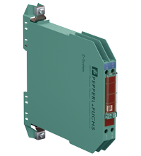
Zener Barrier Z787
- 2-channel
- DC version, positive polarity
- Working voltage 26.5 V at 10 µA
- Series resistance max. 327 Ω
- Fuse rating 50 mA
- DIN rail mountable
- With diode return


Please note: All product-related documents, such as certificates, declarations of conformity, etc., which were issued prior to the conversion under the name Pepperl+Fuchs GmbH or Pepperl+Fuchs AG, also apply to Pepperl+Fuchs SE.
Download the complete datasheet as a PDF:
Datasheet excerpt: Technical data of Z787
| General specifications | ||
|---|---|---|
| Type | DC version, positive polarity | |
| Electrical specifications | ||
| Nominal resistance | 300 Ω | |
| Series resistance | terminals 1, 8: max. 327 Ω | |
| Voltage drop | terminals 4, 5: 1.2 V + (36 Ω x signal current) | |
| Fuse rating | 50 mA | |
| Hazardous area connection | ||
| Connection | terminals 1, 2; 3, 4 | |
| Safe area connection | ||
| Connection | terminals 5, 6; 7, 8 | |
| Working voltage | ||
| Supply loop | max. 27 V | |
| Measurement loop | max. 26.5 V at 10 µA | |
| Conformity | ||
| Degree of protection | IEC 60529 | |
| Ambient conditions | ||
| Ambient temperature | -20 ... 60 °C (-4 ... 140 °F) | |
| Storage temperature | -25 ... 70 °C (-13 ... 158 °F) | |
| Relative humidity | max. 75 % , without condensation | |
| Mechanical specifications | ||
| Degree of protection | IP20 | |
| Connection | screw terminals | |
| Core cross section | max. 2 x 2.5 ... mm2 | |
| Mass | approx. 150 g | |
| Dimensions | 12.5 x 115 x 116 mm (0.5 x 4.5 x 4.6 inch) (W x H x D) | |
| Height | 115 mm | |
| Width | 12.5 mm | |
| Depth | 116 mm | |
| Construction type | modular terminal housing , see system description | |
| Mounting | on 35 mm DIN mounting rail acc. to EN 60715:2001 | |
| Data for application in connection with hazardous areas | ||
| EU-type examination certificate | BAS 01 ATEX 7005 | |
| Marking |  II (1)GD, I (M1) [Ex ia Ga] IIC, [Ex ia Da] IIIC, [Ex ia Ma] I II (1)GD, I (M1) [Ex ia Ga] IIC, [Ex ia Da] IIIC, [Ex ia Ma] I |
|
| Voltage | 28 V | |
| Current | 93 mA | |
| Power | 650 mW | |
| Supply | ||
| Maximum safe voltage | 250 V | |
| Series resistance | min. 301 Ω | |
| Certificate | TÜV 99 ATEX 1484 X | |
| Marking | II 3G Ex nA IIC T4 Gc |
|
| Directive conformity | ||
| Directive 2014/34/EU | EN IEC 60079-0:2018+AC:2020 , EN 60079-11:2012 , EN 60079-15:2010 | |
| International approvals | ||
| FM approval | ||
| Control drawing | 116-0118 | |
| UL approval | ||
| Control drawing | 116-0139 (cULus) | |
| IECEx approval | ||
| IECEx certificate | IECEx BAS 09.0142 IECEx BAS 17.0091X |
|
| IECEx marking | [Ex ia Ga] IIC , [Ex ia Da] IIIC , [Ex ia Ma] I Ex ec IIC T4 Gc |
|
| General information | ||
| Supplementary information | Observe the certificates, declarations of conformity, instruction manuals, and manuals where applicable. For information see www.pepperl-fuchs.com. | |
Classifications
| System | Classcode |
|---|---|
| ECLASS 13.0 | 27211016 |
| ECLASS 12.0 | 27211016 |
| ECLASS 11.0 | 27211016 |
| ECLASS 10.0.1 | 27219001 |
| ECLASS 9.0 | 27219001 |
| ECLASS 8.0 | 27219001 |
| ECLASS 5.1 | 27210702 |
| ETIM 9.0 | EC001485 |
| ETIM 8.0 | EC001485 |
| ETIM 7.0 | EC001485 |
| ETIM 6.0 | EC001485 |
| ETIM 5.0 | EC002653 |
| UNSPSC 12.1 | 39121018 |
Details: Z787
Function
The Zener Barrier prevents the transfer of unacceptably high energy from the safe area into the hazardous area.
The zener diodes in the Zener Barrier are connected in the reverse direction. The breakdown voltage of the diodes is not exceeded in normal operation. If this voltage is exceeded, due to a fault in the safe area, the diodes start to conduct, causing the fuse to blow. The Zener Barrier has a positive polarity, i. e. the anodes of the zener diodes are grounded.
The Zener Barrier is for evaluation of signals from the hazardous area. The diodes of diode return prevent a current into the hazardous area, therefore the current assumption for intrinsic safety calculations is zero.
Depending on the application, increased or decreased intrinsic safety parameters apply for serial or parallel connection. For the detailed parameters refer to the Zener Barrier certificate. Application examples can be found in the system description of the Zener Barriers.
Product Documentation: Z787
| Safety and Security Documentation | Language | File Type | File Size |
|---|---|---|---|
| Instruction manual | ENG | 233 KB | |
| Functional Safety Manual | ENG | 1972 KB | |
| Manuals | |||
| System Manual | ENG | 1203 KB | |
Design / Simulation: Z787
| CAD | Language | File Type | File Size |
|---|---|---|---|
| CAD 3-D / CAD 3-D | ALL | STP | 951 KB |
| CAD Portal / CAD Portal | ALL | LINK | --- |
| CAE | |||
| EPLAN macros Z-System devices (EMA) / EPLAN-Makros Geräte Z-System (EMA) | ALL | ZIP | 2338 KB |
Approvals: Z787
Associated Products: Z787
| Matching System Components | ||||||
|---|---|---|---|---|---|---|
|
||||||
|
||||||
|
||||||
|
||||||
|
||||||
|
||||||
|
||||||
|
||||||
|
||||||
|
||||||


Pepperl+Fuchs SE
Lilienthalstraße 200
68307 Mannheim
Germany
info@de.pepperl-fuchs.com
 +49 621 776-0
Pepperl+Fuchs is a leading developer and manufacturer of electronic sensors and components for the global automation market. Continuous innovation, enduring quality, and steady growth have been the foundation of our success for more than 70 years. Pepperl+Fuchs employs 6,300 people worldwide and has manufacturing facilities in Germany, USA, Singapore, Hungary, Indonesia and Vietnam, most of them ISO 9001 certified.