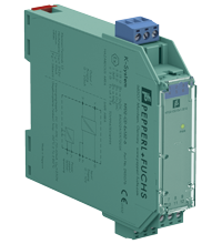
Current Driver KFD2-CD-Ex1.32-6
- 1-channel isolated barrier
- 24 V DC supply (Power Rail)
- Voltage input 0 V ... 10 V
- Current output 0 mA ... 20 mA
- Accuracy 0.1 %
- Up to SIL 2 acc. to IEC/EN 61508
Please note: All product-related documents, such as certificates, declarations of conformity, etc., which were issued prior to the conversion under the name Pepperl+Fuchs GmbH or Pepperl+Fuchs AG, also apply to Pepperl+Fuchs SE.
Download the complete datasheet as a PDF:
Datasheet excerpt: Technical data of KFD2-CD-Ex1.32-6
| General specifications | ||
|---|---|---|
| Signal type | Analog output | |
| Functional safety related parameters | ||
| Safety Integrity Level (SIL) | SIL 2 | |
| Supply | ||
| Connection | Power Rail or terminals 7+, 8- | |
| Rated voltage | 20 ... 35 V DC | |
| Ripple | within the supply tolerance | |
| Rated current | max. 50 mA | |
| Power dissipation | 1.4 W | |
| Input | ||
| Connection side | control side | |
| Connection | terminals 9+, 10-, 11+ | |
| Input current | ≤ 100 µA up to 50 °C (122 °F) at 10 V | |
| Limit | max. 12 V DC | |
| Transmission range | 0 ... 10 V | |
| Output | ||
| Connection side | field side | |
| Connection | terminals 1+, 2- | |
| Voltage | 17 V at 20 mA | |
| Current | 0 ... 20 mA | |
| Load | max. 850 Ω | |
| Transfer characteristics | ||
| Accuracy | 0.1 % | |
| Deviation | ||
| After calibration | ≤ ± 0.1 % incl. non-linearity and hysteresis at 20 °C (68 °F) | |
| Influence of ambient temperature | ≤ ± 0.01 %/K | |
| Rise time | < 10 ms | |
| Galvanic isolation | ||
| Input/power supply | functional insulation, rated insulation voltage 50 V AC | |
| Indicators/settings | ||
| Display elements | LED | |
| Labeling | space for labeling at the front | |
| Directive conformity | ||
| Electromagnetic compatibility | ||
| Directive 2014/30/EU | EN 61326-1:2013 (industrial locations) | |
| Conformity | ||
| Degree of protection | IEC 60529:2001 | |
| Protection against electrical shock | UL 61010-1:2012 | |
| Ambient conditions | ||
| Ambient temperature | -20 ... 60 °C (-4 ... 140 °F) | |
| Mechanical specifications | ||
| Degree of protection | IP20 | |
| Connection | screw terminals | |
| Mass | approx. 100 g | |
| Dimensions | 20 x 107 x 115 mm (0.8 x 4.2 x 4.5 inch) (W x H x D) , housing type B1 | |
| Height | 107 mm | |
| Width | 20 mm | |
| Depth | 115 mm | |
| Mounting | on 35 mm DIN mounting rail acc. to EN 60715:2001 | |
| Data for application in connection with hazardous areas | ||
| EU-type examination certificate | BAS 02 ATEX 7203 X | |
| Marking |  II (1)G [Ex ia Ga] IIC , II (1)G [Ex ia Ga] IIC ,  II (1)D [Ex ia Da] IIIC , II (1)D [Ex ia Da] IIIC ,  I (M1) [Ex ia Ma] I I (M1) [Ex ia Ma] I |
|
| Certificate | TÜV 99 ATEX 1499 X | |
| Marking |  II 3G Ex nA II T4 II 3G Ex nA II T4 |
|
| Directive conformity | ||
| Directive 2014/34/EU | EN 60079-0:2012+A11:2013 , EN 60079-11:2012 , EN 60079-15:2010 | |
| International approvals | ||
| FM approval | ||
| Control drawing | 116-0440 | |
| UL approval | ||
| Control drawing | 116-0441 (cULus) | |
| IECEx approval | ||
| IECEx certificate | IECEx BAS 05.0041X IECEx CML 19.0051X |
|
| IECEx marking | [Ex ia Ga] IIC , [Ex ia Da] IIIC , [Ex ia Ma] I Ex ec IIC T4 Gc |
|
| General information | ||
| Supplementary information | Observe the certificates, declarations of conformity, instruction manuals, and manuals where applicable. For information see www.pepperl-fuchs.com. | |
Classifications
| System | Classcode |
|---|---|
| ECLASS 13.0 | 27210120 |
| ECLASS 12.0 | 27210120 |
| ECLASS 11.0 | 27210120 |
| ECLASS 10.0.1 | 27210120 |
| ECLASS 9.0 | 27210120 |
| ECLASS 8.0 | 27210120 |
| ECLASS 5.1 | 27210120 |
| ETIM 9.0 | EC002653 |
| ETIM 8.0 | EC002653 |
| ETIM 7.0 | EC002653 |
| ETIM 6.0 | EC002653 |
| ETIM 5.0 | EC001485 |
| UNSPSC 12.1 | 32101514 |
Details: KFD2-CD-Ex1.32-6
Function
This isolated barrier is used for intrinsic safety applications.
The device drives I/P converters, electrical valves, and positioners in the hazardous area.
The device has voltage input and current output.
The signal is transmitted to terminals 9 and 10 across an amplifier and the DC/DC converter within the allowable voltage range. A voltage limiter circuit protects the amplifier from incorrect input switching and overvoltage, but will draw current through a 50 mA fuse during operation. The fuse can be changed only by the manufacturer.
The open circuit voltage is 24 V DC within the allowable supply voltage range at terminals 1 and 2. The maximum load that can be applied is 850 Ω.
Product Documentation: KFD2-CD-Ex1.32-6
| Safety and Security Documentation | Language | File Type | File Size |
|---|---|---|---|
| Instruction manual | ENG | 50 KB | |
| Manuals | |||
| Manual | ENG | 3685 KB | |
Design / Simulation: KFD2-CD-Ex1.32-6
| CAD | Language | File Type | File Size |
|---|---|---|---|
| CAD 3-D / CAD 3-D | ALL | STP | 105 KB |
Approvals: KFD2-CD-Ex1.32-6
| Certificates | Certificate No. | Language | File Type | File Size |
|---|---|---|---|---|
| Australia Test Safe | ANZEx 17.3006X | ALL | 6788 KB | |
| Baseefa IECEx Certificate of Conformity | IECEx BAS 05.0041X | ALL | LINK | --- |
| CML Ex ec IECEx Certificate of Conformity | IECEx CML 19.0051X | ALL | LINK | --- |
| Canada UL cUL | E106378 cUL (QUZW7) | ALL | LINK | --- |
| China NEPSI | GYJ19.1230 | ALL | 2098 KB | |
| Europe Baseefa II (1) D I (M1) II (1) G | BAS 02 ATEX 7203X | ALL | 3195 KB | |
| Europe TUV Nord ATEX Category 3 G | TÜV 99 ATEX 1499X | ALL | 1999 KB | |
| Korea KOSHA | 11-AV4BO-0062 | ALL | 570 KB | |
| USA Canada UL Hazardous Location Certificate of Compliance cULus UL E106378 | CoC 20181231 - E106378 RepRef 20181109 | ALL | 404 KB | |
| USA FM | FM 17 US 0334X | ALL | 168 KB | |
| USA UL | E106378 UL (QUZW) | ALL | LINK | --- |
| Ukraine SERTIS Ex | SC 21.0646 X | ALL | 12351 KB | |
| Control Drawings | ||||
| Control drawing UL / Control drawing UL | ALL | 23 KB | ||
| Control drawing FM / Control drawing FM | ALL | 21 KB | ||
Associated Products: KFD2-CD-Ex1.32-6
| Matching System Components | ||||||
|---|---|---|---|---|---|---|
|
||||||
|
||||||
|
||||||
|
||||||
|
||||||
|
||||||
| Accessories | ||||||
|
||||||
|
||||||
|
||||||




 +49 621 776-0