

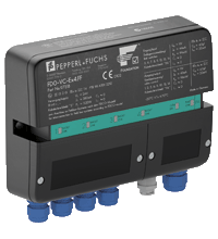
Valve Coupler FD0-VC-EX4.FF
- For four intrinsically safe valves with position sensors
- Installation in Zone 1 and Zone 2
- Valves in Zone 0
- Connection to fieldbus acc. to FISCO or Entity
- For FOUNDATION Fieldbus H1
- PCS integration via device description and function blocks
- Monitors lead breakage and short circuits
- Valve monitoring and diagnostics integrated
- Conducts partial stroke testing


Please note: All product-related documents, such as certificates, declarations of conformity, etc., which were issued prior to the conversion under the name Pepperl+Fuchs GmbH or Pepperl+Fuchs AG, also apply to Pepperl+Fuchs SE.
Download the complete datasheet as a PDF:
Datasheet excerpt: Technical data of FD0-VC-EX4.FF
| General specifications | ||
|---|---|---|
| Design / Mounting | Outside installation | |
| Fieldbus connection | ||
| FOUNDATION Fieldbus | ||
| Connection | Connection +, - | |
| Rated voltage | 9 ... 32 V | |
| Rated current | max. 23 mA | |
| Baud rate | 31.25 kBit/s | |
| Protocol | IEC 61158-2 | |
| Terminal "S" | only for the connection of the cable screen (BUS) and/or the potential compensation | |
| Terminal "PA" | only for the connection of the cable screen (sensor interface) and/or grounding | |
| Grounding plate | only for the connection of the potential compensation | |
| Field circuit | ||
| Inputs | ||
| Connection | 8, for binary sensors: terminals 3, 4, 7, 8, 11, 12, 15, 16 | |
| Sensor supply voltage | 5 V | |
| Sensor supply current | 5 mA | |
| Time delay before availability | 2 ms | |
| Max. cycle time | max. 160 ms | |
| Outputs | ||
| Connection | terminals 1+, 2-; 5+, 6-; 9+, 10-; 13+, 14- | |
| Output voltage | 6.4 ... 7.9 V | |
| Output rated operating current | 1.5 mA | |
| Holding current | 1 mA | |
| Galvanic isolation | ||
| Foundation Fieldbus/Field circuit | safe galvanic isolation acc. to EN 50020, voltage peak value 60 V | |
| Directive conformity | ||
| Electromagnetic compatibility | ||
| Directive 2014/30/EU | EN 61326-1:2013 | |
| Standard conformity | ||
| Galvanic isolation | EN 60079-11 | |
| Electromagnetic compatibility | NE 21:2006 | |
| Degree of protection | IEC/EN 60529 | |
| Fieldbus standard | EN 50170/2 | |
| Ambient conditions | ||
| Ambient temperature | -20 ... 70 °C (-4 ... 158 °F) | |
| Storage temperature | -40 ... 85 °C (-40 ... 185 °F) | |
| Corrosion resistance | acc. to ISA-S71.04-1985, severity level G3 | |
| Mechanical specifications | ||
| Core cross-section | Bus cable: ∅ 5 mm ... 10 mm cable sensors/valve: ∅ 4 mm ... 8 mm |
|
| Housing | 187 mm x 129 mm x 46 mm | |
| Degree of protection | IP65 | |
| Installation position | Cable glands downwards | |
| Mass | approx. 290 g | |
| Mounting | wall mounting | |
| Data for application in connection with hazardous areas | ||
| EU-Type Examination Certificate | PTB 98 ATEX 2210 | |
| Marking |  II 2G (1) Ex ia [ia Ga] IIC T4 Gb , II (1D) [Ex ia Da] IIIC , II 3G Ex ic IIC T4 Gc , II (3D) [Ex ic Dc] IIIC II 2G (1) Ex ia [ia Ga] IIC T4 Gb , II (1D) [Ex ia Da] IIIC , II 3G Ex ic IIC T4 Gc , II (3D) [Ex ic Dc] IIIC |
|
| Field-side | ||
| Voltage | 9 V | |
| Current | 44 mA | |
| Power | 99 mW | |
| FOUNDATION Fieldbus | ||
| Voltage | 24 V | |
| Current | 380 mA | |
| Power | 5.32 W | |
| Rated voltage | 9 ... 32 V | |
| Rated current | 23 mA | |
| FDE (Fault Disconnect Equipment) | 6.7 mA | |
| Terminal "S" | only for the connection of the cable screen (BUS) and/or the potential compensation | |
| Terminal "PA" | only for the connection of the cable screen (sensor interface) and/or grounding | |
| Grounding plate | only for the connection of the potential compensation | |
| Directive conformity | ||
| Directive 2014/34/EU | EN 60079-0:2012 , EN 60079-11:2012 | |
| International approvals | ||
| IECEx approval | IECEx TUN 04.0002 | |
| Approved for | Ex ia [ia Ga] IIC T4 Gb , [Ex ia Da] IIIC , Ex ic IIC T4 Gc , [Ex ic Dc] IIIC |
|
Classifications
| System | Classcode |
|---|---|
| ECLASS 13.0 | 27242610 |
| ECLASS 12.0 | 27242610 |
| ECLASS 11.0 | 27242610 |
| ECLASS 10.0.1 | 27242610 |
| ECLASS 9.0 | 27242610 |
| ECLASS 8.0 | 27242610 |
| ECLASS 5.1 | 27242610 |
| ETIM 9.0 | EC001601 |
| ETIM 8.0 | EC001601 |
| ETIM 7.0 | EC001601 |
| ETIM 6.0 | EC001601 |
| ETIM 5.0 | EC001604 |
| UNSPSC 12.1 | 39121008 |
Details: FD0-VC-EX4.FF
Function
The valve coupler for FOUNDATION Fieldbus H1 connects up to four intrinsically safe low-power valves to the DCS via fieldbus. It is installed pre-wired in a field enclosure or directly outside, close to the valves in the hazardous area. The valve coupler drives four low-power auxiliary valves and gathers positioning information via pairs of inductive proximity switches.
The valve coupler communicates all data, configuration, and alarms via one fieldbus address to the DCS. It supports function blocks via device description. Fieldbus powers the actors, sensors and the valve coupler itself. Additional power or wiring is not required.
The valve coupler supports summary diagnostics according to NAMUR recommendations, and detects lead breakage and short circuit conditions. It monitors and reports runtime and breakaway time during each operation and can conduct partial stroke tests.
Informative Literature: FD0-VC-EX4.FF
| Literature | Language | File Type | File Size |
|---|---|---|---|
| Application Report - Controlling and Monitoring liquid Helium at the Deutsches Elektronen-Synchrotron | ENG | 361 KB | |
| Application Report - Digital Communication in Steel-Plate Manufacturing | ENG | 470 KB |
Product Documentation: FD0-VC-EX4.FF
| System Descriptions | Language | File Type | File Size |
|---|---|---|---|
| Planning and integration: Compatibility list of sensors and pilot valves | ENG | 50 KB | |
| Manuals | |||
| Manual FD0-VC-Ex4.FF | ENG | 1054 KB | |
Approvals: FD0-VC-EX4.FF
| Certificates | Certificate No. | Language | File Type | File Size |
|---|---|---|---|---|
| Europe PTB II 2 G (1) II (1D) II (3D) II 3 G ATEX | PTB 98 ATEX 2210 | ALL | 1378 KB | |
| TUV Nord IECEx Certificate of Conformity | IECEx TUN 04.0002 | ALL | LINK | --- |
| Worldwide Fieldbus Foundation | IT035200 | ALL | 257 KB | |
| Declaration of Conformity | ||||
| EU Declaration of Conformity (P+F) / EU-Konformitäterklärung (P+F) | DOC-0812B | ALL | 88 KB | |
Software: FD0-VC-EX4.FF
| Device Description Files/Drivers | Release Info | File Type | File Size |
|---|---|---|---|
| DD/CFF files, Device Revision 1 / DD/CFF-Dateien, Device Revision 1 | 0102/010201 | ZIP | 47 KB |
| DD/CFF files, Device Revision 2, DD Revision 2 / DD/CFF-Dateien, Device Revision 2, DD Revision 2 | 0202/020103 | ZIP | 57 KB |


Pepperl+Fuchs SE
Lilienthalstraße 200
68307 Mannheim
Germany
info@de.pepperl-fuchs.com
 +49 621 776-0
Pepperl+Fuchs is a leading developer and manufacturer of electronic sensors and components for the global automation market. Continuous innovation, enduring quality, and steady growth have been the foundation of our success for more than 70 years. Pepperl+Fuchs employs 6,300 people worldwide and has manufacturing facilities in Germany, USA, Singapore, Hungary, Indonesia and Vietnam, most of them ISO 9001 certified.