

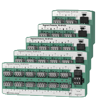
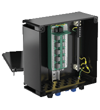
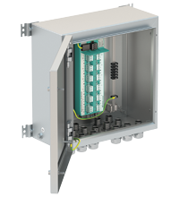
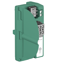
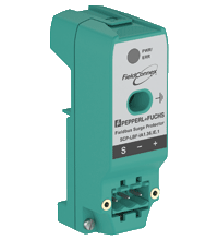
Segment Protector for Cabinet Installation R2-SP-IC*
- 4 ... 12 outputs Ex ic (FISCO or Entity) or non-incendive (Div 2)
- Advanced fault isolation at the spur
- Segment Protector in Zone 2/Div. 2
- Instruments in Zone 2/Div. 2 or Zone 1/Div. 1
- For FOUNDATION Fieldbus H1 and PROFIBUS PA
- Advanced Diagnostics at the spur
- Power, Com, Diagnostics, and Error LEDs
- T-connector for easy installation and maintenance
- Test points for easy troubleshooting


Please note: All product-related documents, such as certificates, declarations of conformity, etc., which were issued prior to the conversion under the name Pepperl+Fuchs GmbH or Pepperl+Fuchs AG, also apply to Pepperl+Fuchs SE.
Download the complete datasheet as a PDF:
Datasheet excerpt: Technical data of R2-SP-IC*
| General specifications | ||
|---|---|---|
| Design / Mounting | Cabinet installation | |
| Fieldbus connection | ||
| Main cable (Trunk) | ||
| Rated voltage | 9 ... 31 V DC 10.5 V DC minimum input voltage acc. to FF-846 |
|
| Rated current | max. 4.5 A | |
| Outputs | ||
| Number of outputs | see table "Technical data depending on model" | |
| Number of devices per output | 1 | |
| Rated voltage | max. 31 V | |
| Rated current | max. 32 mA switch 1, position 1 max. 43 mA switch 1, position 2 |
|
| Short-circuit current | 46 mA switch 1, position 1 57 mA switch 1, position 2 |
|
| Self current consumption | see table "Technical data depending on model" | |
| Voltage drop main cable/outputs | max. 1.2 V | |
| Voltage drop trunk In/Out | 0 V | |
| Terminating resistor | external type M-FT 100 Ω +/- 10 % | |
| Surge protection | Trunk overvoltage protection if voltage exceeds typ. 39 V, max. 41 V | |
| Indicators/operating means | ||
| Switch | configuration of short-circuit current/rated current | |
| LED PWR | green: Fieldbus voltage > 10 V and fieldbus terminator is deactivated | |
| LED COM/ERR | yellow: flashing: fieldbus communication status and physical layer diagnostic status | |
| LED SPURS | red: 2 Hz flashing in short-circuit condition | |
| Directive conformity | ||
| Electromagnetic compatibility | ||
| Directive 2014/30/EU | EN 61326-1:2013 | |
| Standard conformity | ||
| Electromagnetic compatibility | NE 21:2011 | |
| Degree of protection | IEC 60529 | |
| Fieldbus standard | IEC 61158-2 | |
| Climatic conditions | IEC 60721 | |
| Shock resistance | EN 60068-2-27 | |
| Vibration resistance | EN 60068-2-6 | |
| Ambient conditions | ||
| Ambient temperature | -50 ... 70 °C (-58 ... 158 °F) | |
| Storage temperature | -50 ... 85 °C (-58 ... 185 °F) | |
| Relative humidity | < 95 % non-condensing | |
| Shock resistance | 15 g 11 ms | |
| Vibration resistance | 1 g , 10 ... 150 Hz | |
| Corrosion resistance | acc. to ISA-S71.04-1985, severity level G3 | |
| Mechanical specifications | ||
| Connection type | pluggable , screw terminal or spring terminal | |
| Core cross section | see table 2 | |
| Housing material | Polycarbonate | |
| Degree of protection | IP20 | |
| Mass | see table "Technical data depending on model" | |
| Dimensions | see table "Technical data depending on model" | |
| Mounting | DIN rail mounting | |
| Data for application in connection with hazardous areas | ||
| EU-type examination certificate | TÜV 12 ATEX 098651 X | |
| Marking |  II 3G Ex nA [ic] IIC T4 Gc II (3)D [Ex ic Dc] IIIC II 3G Ex nA [ic] IIC T4 Gc II (3)D [Ex ic Dc] IIIC |
|
| Supply | ||
| Maximum safe voltage | 35 V | |
| Outputs | ||
| Voltage | 32 V | |
| Current | 46 mA switch 1, position 1 65 mA switch 1, position 2 |
|
| Inductance | 0.125 mH switch 1, position 1 0.25 mH switch 1, position 2 |
|
| Capacitance | 60 nF | |
| Directive conformity | ||
| Directive 2014/34/EU | EN IEC 60079-0:2018+AC:2020 , EN 60079-11:2012 , EN 60079-15:2010 | |
| International approvals | ||
| UL approval | E106378 | |
| Control drawing | 116-0406 | |
| Approved for | Class I, Division 2, Groups A, B, C, D | |
| IECEx approval | IECEx TUN 12.0015X | |
| Approved for | Ex nA [ic] IIC T4 Gc [Ex ic Dc] IIIC |
|
| General information | ||
| Supplementary information | Statement of Conformity, Declaration of Conformity, Attestation of Conformity and instructions have to be observed where applicable. For information see www.pepperl-fuchs.com. | |
Classifications
| System | Classcode |
|---|---|
| ECLASS 13.0 | 27242610 |
| ECLASS 12.0 | 27242610 |
| ECLASS 11.0 | 27242610 |
| ECLASS 10.0.1 | 27242610 |
| ECLASS 9.0 | 27242610 |
| ECLASS 8.0 | 27242610 |
| ECLASS 5.1 | 27242601 |
| ETIM 9.0 | EC001601 |
| ETIM 8.0 | EC001601 |
| ETIM 7.0 | EC001601 |
| ETIM 6.0 | EC001601 |
| ETIM 5.0 | EC001604 |
| UNSPSC 12.1 | 39121008 |
Details: R2-SP-IC*
Function
The R2 Segment Protector with integrated diagnostics, a device coupler for DIN rail installation, connects 4 ... 12 instruments to the segment with intrinsic safety (Ex ic, Zone 2/Div. 2). Device connections in Zone 1/Div. 1 require additional methods of ignition protection. Short-circuit, jabber, and bounce protection isolates most fault condition types from the segment. The short-circuit limit is adjustable for maximum load with Ex ic for gas groups IIB and IIC.
The T-connector at the trunk allows for exchange of a Segment Protector with no effect on the remaining segment. The terminator is mounted at the 'T' and removed for network extensions ensuring proper termination.
Short circuit protection ensures proper operation of the segment in case of unwanted faults at the spur. Intrinsic safety at the spur enables work on devices with hot work permit. The integrated fieldbus terminator features a high-availability design.
Informative Literature: R2-SP-IC*
| Literature | Language | File Type | File Size |
|---|---|---|---|
| Application Report - Controlling and Monitoring liquid Helium at the Deutsches Elektronen-Synchrotron | ENG | 361 KB | |
| Application Report - Digital Communication in Steel-Plate Manufacturing | ENG | 470 KB | |
| Application Report - Intelligent Fault Protection between Segment and Field | ENG | 210 KB |
Product Documentation: R2-SP-IC*
| System Descriptions | Language | File Type | File Size |
|---|---|---|---|
| Conformity matrix for R2-SP-IC* and F2-SP-IC* with motherboards: MB*-, MBHD*, FBTA-228-BPFB-8, FBTA-228-BPFB-R-4R and power supply modules: HD2-FBPS-* | ENG | 73 KB | |
| Conformity matrix for R2-SP-IC* and F2-SP-IC* with motherboards: MBHC*, FBTA-228-BPFB-R-8R and power supply modules: HCD2-FBPS-* | ENG | 143 KB | |
| Safety and Security Documentation | |||
| Instruction manual | ENG | 229 KB | |
| Manuals | |||
| Manual | ENG | 3049 KB | |
Design / Simulation: R2-SP-IC*
| CAD | Language | File Type | File Size |
|---|---|---|---|
| DXF drawings / DXF Zeichungen | ALL | ZIP | 1975 KB |
Approvals: R2-SP-IC*
| Certificates | Certificate No. | Language | File Type | File Size |
|---|---|---|---|---|
| Brasil TUV Rheinland Brazil | TÜV 14.1593 X | ALL | 1122 KB | |
| China SITIIAS CCC Ex Certificate | 2020322310002500 (Singapore) | ALL | 1291 KB | |
| DNV Marine | TAA0000272 | ALL | 100 KB | |
| Europe TUV Nord II 3 G | TUV 12 ATEX 098651 X | ALL | 664 KB | |
| India PESO (India) CCOE | A/P/HQ/KA/104/6086 (P576914) | ALL | 105 KB | |
| TUV Nord Zone 2 IECEx Certificate of Conformity | IECEx TUN 12.0015X | ALL | LINK | --- |
| USA Canada UL Hazardous Location Certificate of Compliance cULus UL E106378 | CoC E106378 RepRef E106378-20141126 | ALL | 413 KB | |
| Worldwide Fieldbus Foundation | DC084300 | ALL | 56 KB | |
| Control Drawings | ||||
| Control drawing UL / Control drawing UL | ALL | 389 KB | ||
| Declaration of Conformity | ||||
| EU Declaration of Conformity (P+F) / EU-Konformitäterklärung (P+F) | DOC-0603D | ALL | 1042 KB | |
Associated Products: R2-SP-IC*
| Matching System Components | ||||||
|---|---|---|---|---|---|---|
|
||||||
|
||||||
| Accessories | ||||||
|
||||||
|
||||||


Pepperl+Fuchs SE
Lilienthalstraße 200
68307 Mannheim
Germany
info@de.pepperl-fuchs.com
 +49 621 776-0
Pepperl+Fuchs is a leading developer and manufacturer of electronic sensors and components for the global automation market. Continuous innovation, enduring quality, and steady growth have been the foundation of our success for more than 70 years. Pepperl+Fuchs employs 6,300 people worldwide and has manufacturing facilities in Germany, USA, Singapore, Hungary, Indonesia and Vietnam, most of them ISO 9001 certified.