

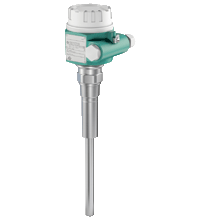
Vibration Limit Switch LVL-B1
- Limit switch for bulk solids
- Compact device
- No calibration: easy commissioning (plug and play)
- Insensitive to build-up: maintenance-free operation
- No mechanically moving parts: no wear, long operating life
- Sensor material stainless steel: hardly any abrasion even with building materials
- Insensitive to external vibration and flow noises


Please note: All product-related documents, such as certificates, declarations of conformity, etc., which were issued prior to the conversion under the name Pepperl+Fuchs GmbH or Pepperl+Fuchs AG, also apply to Pepperl+Fuchs SE.
Download the complete datasheet as a PDF:
Datasheet excerpt: Technical data of LVL-B1
| General specifications | ||
|---|---|---|
| Measuring method | A piezoelectric drive excites the vibrating rod of the device to its resonance frequency. If medium covers the vibrating rod, the rod's vibrating amplitude changes (the vibration is damped). The electronics of the device compare the actual amplitude with a target value and indicates whether the vibrating rod is vibrating freely or whether it is covered by medium. | |
| Equipment architecture | The measuring system consists of: - the device with electronic insert - a supply point - the connected control systems, switching units, signalling systems (e. g. lamps, horns, PCS, PLC, etc.) |
|
| Construction type | compact device | |
| Operating mode | MAX = maximum safety: The device switches if the probe is covered or if the supply voltage is disconnected in a safety-oriented manner (signal on alarm). example application: overspill protection MIN = minimum safety: The device switches if the probe is uncovered or if the supply voltage is disconnected in a safetyoriented manner (signal on alarm). example application: dry-running protection |
|
| Series | Vibracon LVL-B1 | |
| Supply | ||
| Rated voltage | electronic insert FEM22 (E5): 10 ... 45 V DC electronic insert FEM24 (WA): 19 ... 253 V AC, 50/60 Hz or 19 ... 55 V DC |
|
| Ripple | electronic insert FEM22 (E5): max. 5 V, 0 ... 400 Hz | |
| Current consumption | electronic insert FEM22 (E5): max. 18 mA | |
| Power consumption | electronic insert FEM22 (E5): max. 0.81 W electronic insert FEM 24 (WA): max. 1.3 W |
|
| Reverse polarity protection | separation voltage 2.2 kV | |
| Electrical specifications | ||
| Surge protection | electronic insert FEM22 (E5) : overvoltage category III | |
| Input | ||
| Input signal | probe covered - small amplitude probe not covered - large amplitude |
|
| Measured variable | level (according to the mounting location and the overall length) | |
| Measurement range | The measuring range depends on the mounting location of the device | |
| Output | ||
| Load | electronic insert FEM22 (E5): - load switched via transistor and separate PNP connection - load current: max. 45 V (cyclical overload and short-circuit protection), continuous max. 350 mA - residual current: < 100 µA (for blocked transistor) - capacitive load: max. 0.5 µF for 45 V, max. 1.0 µF for 24 V - residual voltage: < 3 V (for transistor switched through) electronic insert FEM24 (WA): - loads switched via 2 floating change-over contacts - version AC: I max. 6 A, U max. 253 V; P max. 1500 VA, cos φ = 1, P max. 750 VA, cos φ > 0.7 - version DC: I max. 6 A to 30 V, I max. 0.2 A to 125 V - the following applies when connecting a functional extra-low voltage circuit with double insulation as per IEC 1010: sum of voltages of relay output and power supply max. 300 V |
|
| Switch-on delay | correct switching after max. 3 s | |
| Output signal | digital | |
| Signal on alarm | electronic insert FEM22 (E5): output signal on power failure or in the event of device failure - < 100 µA electronic insert FEM24 (WA): output signal in event of power failure - relay de-energised |
|
| Galvanic isolation | ||
| Input/power supply | electronic insert FEM22 (E5) | |
| Input/Other circuits | electronic insert FEM24 (WA) | |
| Directive conformity | ||
| Electromagnetic compatibility | ||
| Directive 2014/30/EU | EN 61326-1:2006 , EN 61326-2-3:2006 | |
| Low voltage | ||
| Directive 2014/35/EU | electronic insert FEM24 (WA) : EN 61010-1:2010 | |
| Conformity | ||
| Electromagnetic compatibility | NE 21 | |
| Degree of protection | IEC 60529:2001 | |
| Vibration resistance | EN 60068-2-27 | |
| Climate class | EN 60068, part 2-38, fig. 2a | |
| Measurement accuracy | ||
| Measuring frequency | 700 ... 800 Hz | |
| Switching time | when covering the sensor approx. 0.5 s, when uncovering the sensor approx. 1.0 s | |
| Operating conditions | ||
| Installation conditions | ||
| Installation position | see section mounting position | |
| Process conditions | ||
| Process temperature | -40 ... 150 °C (-40 ... 302 °F) | |
| Medium pressure limits | -1 ... 25 bar max. working pressure 25 bar, burst pressure 100 bar |
|
| Thermal shock resistance | max. 120 K | |
| State of aggregation | solids | |
| Solid contents | ≤ ∅25 mm | |
| Bulk density | ≥ 200 g/l, not fluidised | |
| Ambient conditions | ||
| Ambient temperature | -40 ... 70 °C (-40 ... 158 °F) | |
| Storage temperature | -40 ... 85 °C (-40 ... 185 °F) | |
| Mechanical specifications | ||
| Degree of protection | IP66/IP67, NEMA 4X | |
| Connection | gland M20 thread G1/2, NPT1/2 |
|
| Material | F16 housing: PTB-FR, cover with transparent glass made of PA12, EPDM cover seal F18 housing: aluminum EN-AC-AlSi10Mg, plastic coated cover seal: EPDM process connections, sensor: stainless steel 1.4435/316L |
|
| Mass | device with F16 housing, electronic insert FEM24 (WA) and R1 thread: approx. 1.0 kg | |
| Dimensions | max. ∅85 mm (3.3 inch), length 372 mm (14.6 inch) | |
| Process connection | thread R1, R1-1/2 acc. to DIN 2999 thread 1-1/4 - 11-1/2 NPT, 1-1/2 - 11-1/2 NPT acc. to ANSI B 1.20.1 |
|
| Data for application in connection with hazardous areas | ||
| EU-type examination certificate | see instruction manuals (SI) | |
| International approvals | ||
| IECEx approval | IECEx DEK 11.0068 | |
| Approved for | Ex ta/tc IIIC T170°C Da/Dc | |
| General information | ||
| Supplementary documentation | technical information (TI) manuals, brief instructions (BA, KA) instruction manuals (SI) |
|
| Supplementary information | Observe the certificates, declarations of conformity, instruction manuals, and manuals where applicable. For information see www.pepperl-fuchs.com. | |
Classifications
| System | Classcode |
|---|---|
| ECLASS 13.0 | 27200518 |
| ECLASS 12.0 | 27200518 |
| ECLASS 11.0 | 27200518 |
| ECLASS 10.0.1 | 27200518 |
| ECLASS 9.0 | 27200589 |
| ECLASS 8.0 | 27200589 |
| ECLASS 5.1 | 27200589 |
| ETIM 9.0 | EC001447 |
| ETIM 8.0 | EC001447 |
| ETIM 7.0 | EC001447 |
| ETIM 6.0 | EC001447 |
| ETIM 5.0 | EC001447 |
| UNSPSC 12.1 | 41111950 |
Details: LVL-B1
Function
The device is a robust level limit switch for silos with fine-grained or coarse-grained, non-fluidised bulk solids.
The various designs means the device has a wide range of applications. Certificates are also available for use in dust incendive hazard areas.
Typical applications:
cereals, coffee beans, sugar, animal feed, rice, detergents, dye powder, chalk, gypsum, cement, sand, plastic granules
Product Documentation: LVL-B1
| Product information | Language | File Type | File Size |
|---|---|---|---|
| TI00389O, Technical information LVL-B* | ENG | 1130 KB | |
| Brief Instructions | |||
| KA00227O, brief instructions LVL-B* / KA00227O, Kurzanleitung LVL-B* | ALL | 2503 KB | |
| Safety and Security Documentation | |||
| SI00300O, Instruction manual LVL-B* | ENG | 793 KB | |
| SI00424O, Instruction manual LVL-B* | ENG | 520 KB | |
Approvals: LVL-B1
| Certificates | Certificate No. | Language | File Type | File Size |
|---|---|---|---|---|
| Canada, USA CSA | CoC 1810432 | ALL | 241 KB | |
| DEKRA Ex ta/tc IECEx Certificate of Conformity | IECEx DEK 11.0068 | ALL | LINK | --- |
| Europe KEMA ATEX Category 1/3 D | KEMA 06 ATEX 0055 | ALL | 2310 KB | |
| Declaration of Conformity | ||||
| EU Declaration of Conformity (P+F) / EU-Konformitäterklärung (P+F) | DOC-2217C | ALL | 79 KB | |
| EU Declaration of Conformity (P+F) / EU-Konformitäterklärung (P+F) | DOC-2357C | ALL | 100 KB | |
| EU Declaration of Conformity (P+F) / EU-Konformitäterklärung (P+F) | DOC-2218C | ALL | 77 KB | |
| Contamination Declaration | ||||
| Contamination declaration / Kontaminationserklärung | ALL | 137 KB | ||


Several hundred products with a SIL/PL assessment, free tools, and brochures in one place: the "Functional Safety Hub" is your starting point when you have to implement safety functions.


Pepperl+Fuchs SE
Lilienthalstraße 200
68307 Mannheim
Germany
info@de.pepperl-fuchs.com
 +49 621 776-0
Pepperl+Fuchs is a leading developer and manufacturer of electronic sensors and components for the global automation market. Continuous innovation, enduring quality, and steady growth have been the foundation of our success for more than 70 years. Pepperl+Fuchs employs 6,300 people worldwide and has manufacturing facilities in Germany, USA, Singapore, Hungary, Indonesia and Vietnam, most of them ISO 9001 certified.