

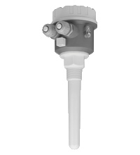
Capacitive limit switch LCL*
- Complete unit consisting of the probe and electronic insert
- Integrated active build-up compensation: exact switch point, even with strong build-up
- Mechanically rugged: no wearing parts, long operating life, maintenance-free
- Rope probe can be shortened for optimum matching to the measuring point
- ATEX approval for zone 20 (dust)


Please note: All product-related documents, such as certificates, declarations of conformity, etc., which were issued prior to the conversion under the name Pepperl+Fuchs GmbH or Pepperl+Fuchs AG, also apply to Pepperl+Fuchs SE.
Download the complete datasheet as a PDF:
Datasheet excerpt: Technical data of LCL*
| Application | ||
|---|---|---|
| Function principle | Limit detection Maximum or minimum detection in silos with all types of solid granulates, even in dust explosion hazardous areas. |
|
| Function and system design | ||
| Measuring principle | A metal plate at the end of the probe, within the insulation, and the surroundings (e. g. the silo walls) combine to form the two electrodes of a capacitor. If the probe is covered or free of material, then the capacitance changes and the LCL switches. | |
| Input characteristics | ||
| Measured variable | limit level (limit value) | |
| Measurement range | LCL1: dielectric constant ≥ 1.6 LCL2: dielectric constant ≥ 1.5 |
|
| Medium | bulk solids, grain size max. 30 mm (1.2 inch), density min. 200 g/l, dielectric constant ≥ 1.6 | |
| Output characteristics | ||
| Output signal | connection E5: switching PNP, Imax = 200 mA - overload and short circuit protection - residual voltage at transistor at Imax < 2.9 V connection WA: contact change-over, potential-free - Umax = 253 V - Imax = 4 A (AC) - Pmax = 1000 VA, cos φ = 1, Pmax = 500 VA, cos φ > 0.7 |
|
| Signal on alarm | connection E5: < 100 µA connection WA: relay de-energized |
|
| Fail-safe mode | minimum/maximum quiescent current safety can be switched at electronic insert connection E5 with PNP output: maximum fail-safe mode: The switch output is blocked when the probe is covered or the power supply fails. minimum fail-safe mode: The switch output is blocked when the probe is free or the power supply fails. connection WA with relay output (potential-free change-over contact): maximum fail-safe mode: The relay is de-energised when the probe is covered or the power supply fails. minimum fail-safe mode: The relay is de-energised when the probe is free or the power supply fails. |
|
| Switching time | LCL1: approx. 0.5 s when covering and uncovering LCL2: approx. 0.8 s when covering and uncovering |
|
| Switch-on response | LCL1: correct switching after max. 1.5 s LCL2: correct switching after max. 2 s |
|
| Auxiliary energy | ||
| Electrical connection | see section electrical connection | |
| Supply voltage | electrical connection E5: 10.8 ... 45 V DC, short-term pulse on 55 V DC electrical connection WA: 20 ... 235 V AC, 50/60 Hz or 20 ... 55 V DC |
|
| Connecting cable | terminal connection: lace max. 1.5 mm2 in end splice, wire max. 2.5 mm2 | |
| Current consumption | electrical connection E5: max. 30 mA, reverse-polarity-proof electrical connection WA: max. 130 mA |
|
| Measurement accuracy | ||
| Reference operating conditions | vessel type: plastic vessel, ambient temperature: 73 °F (23 °C, 296 K), medium temperature: 73 °F (23 °C, 296 K) medium pressure pe: 0 bar, medium: dielectric constant = 2.6, conductivity: < 1 µS sensitivity setting: C |
|
| Hysteresis | LCL1: horizontal 4 mm (0.16 inch), vertical 7 mm (0.28 inch) LCL2: vertical 5 mm (0.2 inch) |
|
| Long-term drift | LCL1: horizontal 3 mm (0.12 inch), vertical 6 mm (0.24 inch) LCL2: vertical 6 mm (0.24 inch) |
|
| Influence of medium temperature | depending on the filling material | |
| Operating conditions | ||
| Installation conditions | ||
| Installation position | LCL1: optional LCL2: vertically down Note the angle of the material mounds and the outlet funnel when determining the mounting point or probe length. The limit switch switches when the probe tip is covered by a few centimetres of material or when it is free material flow should not be directed at the probe. |
|
| Mounting location | The capacitive limit switch can be installed in silos made of different materials (e. g. metal, plastic, concrete). | |
| Ambient conditions | ||
| Ambient temperature | -40 ... 70 °C (-40 ... 158 °F) (-40 ... 140 °F (-40 ... 60 °C, 233 ... 333 K), dust-Ex version) see section temperature ranges |
|
| Ambient temperature limits | -40 ... 80 °C (-40 ... 176 °F) (-40 ... +140 °F (-40 ... +60 °C, 233 ... 333 K), Dust-Ex version) see section temperature ranges , grey background |
|
| Storage temperature | -40 ... 80 °C (-40 ... 176 °F) | |
| Shock resistance | probe: 7J | |
| Overvoltage protected | overvoltage category III | |
| Process conditions | ||
| Process temperature | LCL1: -40 ... 120 °C (233 ... 393 K) (-40 ... 80 °C (233 ... 353 K), dust-Ex version) LCL2: -20 ... 70 °C (253 ... 343 K) see section temperature ranges |
|
| Process temperature limits | LCL1: -40 ... 130 °C (233 ... 403 K) (-40 ... 80 °C (233 ... 353 K), dust-Ex version) LCL2: -40 ... 80 °C (233 ... 353 K) see section temperature ranges , grey background |
|
| Medium pressure limits | LCL1: -1 ... 25 bar LCL2: -1 ... 6 bar |
|
| Mechanical specifications | ||
| Degree of protection | IP66 | |
| Mechanical construction | ||
| Construction type | LCL1: compact version with rod probe LCL2: version with rope probe |
|
| Dimensions | housing: LCL1 Ø94 x 140 mm (3.7 x 5.5 inch), LCL2 Ø94 x 145 mm (3.7 x 5.7 inch) process connections: see section dimensions probe: LCL1 length 140 mm (5.5 inch), LCL2 length 500 ... 6000 mm (1.7 ... 20 ft) |
|
| Mass | LCL1: 560 g LCL2: 1230 g (basic weight for 500 mm probe length) |
|
| Material | housing: PBT-FR with cover in PBT-FR or with transparent cover in PA12, seal of cover: EPDM cable gland: polyamide or brass, nickel-plated wetted parts: - rod probe: PPS Polyphenylenesulphide (glass fiber content 40 %) - rope probe: armoured steel with HD-PE coating - other probe components: PPS Polyphenylenesulphide (glass fiber content 40 %) |
|
| Mechanical load | LCL1: flexural strength 1400 N (at probe tip) LCL2: tensile strength max. 3000 N up to 40 °C (313 K), max. 2800 N at 80 °C (353 K) |
|
| Switching point | sensor switch points depend on the mounting location in relation to the reference operating conditions LCL1: horizontal centre of probe -5 mm (-0.2 inch), vertical 40 mm (1.6 inch) above tip of the probe LCL2: vertical 35 mm (1.4 inch) above tip of the probe |
|
| Process connection | - conical thread R1, R1-1/2 to DIN 2999, part 1 - conical thread NPT1, NPT1-1/2 to ANSI B 1.20.1 |
|
| Indication and operation | ||
| Display elements | green LED: standby indication red LED: switch status indication |
|
| Control elements | switch on electronic insert - switching between minimum and maximum fail-safe mode - sensitivity setting (depends on the dielectric constant and build-up). A sensitivity adjustment is normally not required. |
|
| Certificates and approvals | ||
| Explosion-hazardous area | LCL1: DMT 01 ATEX E 122, LCL2: KEMA 01 ATEX 1149 , for additional certificates see www.pepperl-fuchs.com | |
| Type of protection |  II 1/3D IP66 T97°C (DMT 01 ATEX E122) II 1/3D [EEx ia] IIB T97°C (KEMA 01 ATEX 1149) II 1/3D IP66 T97°C (DMT 01 ATEX E122) II 1/3D [EEx ia] IIB T97°C (KEMA 01 ATEX 1149) |
|
| Overspill protection | LCL1: Z-65.13-313 (overspill protection in acc. with WHG) | |
| General information | ||
| Directive conformity | ||
| Directive 73/23/EEC | EN 61010-1 | |
| Directive 89/336/EEC (EMC) | emitted interference to EN 61326, class B equipment noise immunity to EN 61326, annex A (industrial sector) |
|
| Directive 94/9/EC (ATEX) | EN 50014, EN 50020, EN 50281-1-1 | |
| Conformity | ||
| Electromagnetic compatibility | NE 21 | |
| Degree of protection | EN 60529 | |
| Climate class | EN 60068, part 2-38, fig. 2a | |
| Vibration resistance | EN 60068-2-64, 20 ... 2000 Hz, spectrale rate of velocity 0.5, 100 min per axis | |
| Supplementary documentation | technical information TI-LCL operating instructions KA093O (LCL1) operating instructions KA094O optimising performance (LCL1) operating instructions KA098O adapter for LCL1 (LCL-Z11, LCL-Z12) operating instructions KA099O transparent cover (LCL-Z10) operating instructions KA155O (LCL2) operating instructions KA156O fail-safe mode (LCL2) operating instructions KA157O rope shortening for LCL2 (LCL-Z14) safety information SI092O (LCL2, KEMA 01 ATEX 1149) safety information SI011O (LCL1, DMT 01 ATEX E 122) approval ZE232O overspill protection (Z-65.13-313) |
|
| Supplementary information | EC-Type Examination Certificate, Statement of Conformity, Declaration of Conformity, Attestation of Conformity and instructions have to be observed where applicable. For information see www.pepperl-fuchs.com. | |
Classifications
| System | Classcode |
|---|---|
| ECLASS 13.0 | 27200503 |
| ECLASS 12.0 | 27200503 |
| ECLASS 11.0 | 27200503 |
| ECLASS 10.0.1 | 27200503 |
| ECLASS 9.0 | 27200503 |
| ECLASS 8.0 | 27200503 |
| ECLASS 5.1 | 27200503 |
| ETIM 9.0 | EC001447 |
| ETIM 8.0 | EC002993 |
| ETIM 7.0 | EC002993 |
| ETIM 6.0 | EC002993 |
| ETIM 5.0 | EC001447 |
| UNSPSC 12.1 | 41111950 |
Details: LCL*
Function
The capacitive limit switch is designed for limit detection of light bulk solids, e. g. grain products, flour, milk powder, animal feed, cement, chalk or plaster.
Versions:
-
LCL1 with 140 mm (5.5 in) rod probe, for bulk solids and liquids
-
LCL2 with rope probe up to 6 m (20 ft), for bulk solids
-
Relay output (potential-free change-over contact) with AC or DC connection
-
PNP output with 3-wire DC connection
Product Documentation: LCL*
| Brief Instructions | Language | File Type | File Size |
|---|---|---|---|
| KA00093O, brief instructions LCL1 / KA00093O, Kurzanleitung LCL1 | ALL | 805 KB | |
| KA00094O, brief instructions LCL1, factory settings / KA00094O, Kurzanleitung LCL1, Werkseinstellung | ALL | 173 KB | |
| KA00098O, Brief instructions adapter R1-1/2, G1-1/2 / KA00098O, Kurzanleitung Adapter R1-1/2, G1-1/2 | ALL | 523 KB | |
| KA00156O, brief instructions LCL2, fail-safe circuit / KA00156O, Kurzanleitung LCL2, Sicherheitsschaltung | ALL | 172 KB | |
| Safety and Security Documentation | |||
| SI00011O, Instruction manual LCL1 | ENG | 881 KB | |
| SI00092O. Instruction manual LCL2 | ENG | 978 KB | |
Approvals: LCL*
| Certificates | Certificate No. | Language | File Type | File Size |
|---|---|---|---|---|
| Canada CSA | CoC 212978 | ALL | 251 KB | |
| Europe DEKRA ATEX Category 1/3 D | KEMA 01 ATEX 1149 | ALL | 943 KB | |
| Europe DEKRA EXAM ATEX Category 1/3 D | DMT 01 ATEX E 122 | ALL | 764 KB | |
| USA FM | CoC 3012925 | ALL | 60 KB | |
| USA FM | CoC 3013716 | ALL | 52 KB | |
| Declaration of Conformity | ||||
| EU Declaration of Conformity (P+F) / EU-Konformitäterklärung (P+F) | DOC-2547B | ALL | 260 KB | |
| EU Declaration of Conformity (P+F) / EU-Konformitäterklärung (P+F) | DOC-2220B | ALL | 261 KB | |
| Contamination Declaration | ||||
| Contamination declaration / Kontaminationserklärung | ALL | 137 KB | ||


Pepperl+Fuchs SE
Lilienthalstraße 200
68307 Mannheim
Germany
info@de.pepperl-fuchs.com
 +49 621 776-0
Pepperl+Fuchs is a leading developer and manufacturer of electronic sensors and components for the global automation market. Continuous innovation, enduring quality, and steady growth have been the foundation of our success for more than 70 years. Pepperl+Fuchs employs 6,300 people worldwide and has manufacturing facilities in Germany, USA, Singapore, Hungary, Indonesia and Vietnam, most of them ISO 9001 certified.