

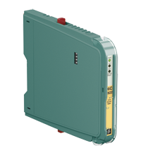
Switch Amplifier HiC2822
- 2-channel isolated barrier
- 24 V DC supply (bus powered)
- Dry contact or NAMUR inputs
- 2 relay contact outputs
- Line fault detection (LFD)
- Reversible mode of operation
- Up to SIL 2 acc. to IEC/EN 61508


Please note: All product-related documents, such as certificates, declarations of conformity, etc., which were issued prior to the conversion under the name Pepperl+Fuchs GmbH or Pepperl+Fuchs AG, also apply to Pepperl+Fuchs SE.
Download the complete datasheet as a PDF:
Datasheet excerpt: Technical data of HiC2822
| General specifications | ||
|---|---|---|
| Signal type | Digital Input | |
| Functional safety related parameters | ||
| Safety Integrity Level (SIL) | SIL 2 | |
| Supply | ||
| Connection | SL1: 1a(-), 1b(-); 2a(+), 2b(+) | |
| Rated voltage | 19 ... 30 V DC bus powered via Termination Board | |
| Ripple | ≤ 10 % | |
| Rated current | ≤ 30 mA | |
| Power dissipation | ≤ 600 mW | |
| Power consumption | ≤ 600 mW | |
| Input | ||
| Connection side | field side | |
| Connection | SL2: 5a(+), 5b(-); 1a(+), 1b(-) | |
| Rated values | acc. to EN 60947-5-6 (NAMUR), see manual for electrical data | |
| Open circuit voltage/short-circuit current | approx. 10 V DC / approx. 8 mA | |
| Switching point/switching hysteresis | 1.2 ... 2.1 mA / approx. 0.2 mA | |
| Line fault detection | breakage I ≤ 0.1 mA , short-circuit I ≥ 6.7 mA | |
| Pulse/Pause ratio | min. 20 ms / min. 20 ms | |
| Output | ||
| Connection side | control side | |
| Connection | SL1: 8a, 7a; 10a, 9a | |
| Output I | signal ; relay | |
| Output II | signal ; relay | |
| Contact loading | 50 V DC / 0.5 A | |
| Minimum switch current | 2 mA / 24 V DC | |
| Energized/De-energized delay | ≤ 20 ms / ≤ 20 ms | |
| Mechanical life | 107 switching cycles | |
| Fault indication output | ||
| Connection | SL1: 6b | |
| Output type | open collector transistor (internal fault bus) | |
| Transfer characteristics | ||
| Switching frequency | ≤ 10 Hz | |
| Galvanic isolation | ||
| Output/power supply | basic insulation acc. to EN 50178, rated insulation voltage of 50 V AC | |
| Output/Output | basic insulation acc. to EN 50178, rated insulation voltage of 50 V AC | |
| Indicators/settings | ||
| Display elements | LEDs | |
| Control elements | DIP switch | |
| Configuration | via DIP switches | |
| Labeling | space for labeling at the front | |
| Directive conformity | ||
| Electromagnetic compatibility | ||
| Directive 2014/30/EU | EN 61326-1:2013 (industrial locations) | |
| Conformity | ||
| Galvanic isolation | EN 50178:1997 | |
| Electromagnetic compatibility | EN IEC 61326-3-2:2018 , NE 21:2012 For further information see system description. |
|
| Degree of protection | IEC 60529:2001 | |
| Input | EN 60947-5-6:2000 | |
| Ambient conditions | ||
| Ambient temperature | -20 ... 60 °C (-4 ... 140 °F) | |
| Mechanical specifications | ||
| Degree of protection | IP20 | |
| Mass | approx. 110 g | |
| Dimensions | 12.5 x 106 x 128 mm (0.5 x 4.2 x 5.1 inch) (W x H x D) | |
| Height | 106 mm | |
| Width | 12.5 mm | |
| Depth | 128 mm | |
| Mounting | on termination board | |
| Coding | pin 1 and 2 trimmed For further information see system description. |
|
| Data for application in connection with hazardous areas | ||
| EU-type examination certificate | BASEEFA 06 ATEX 0093 X | |
| Marking |  II (1)G [Ex ia Ga] IIC II (1)D [Ex ia Da] IIIC I (M1) [Ex ia Ma] I II (1)G [Ex ia Ga] IIC II (1)D [Ex ia Da] IIIC I (M1) [Ex ia Ma] I |
|
| Input | [Ex ia Ga] IIC, [Ex ia Da] IIIC, [Ex ia Ma] I | |
| Voltage | 10.5 V | |
| Current | 17.1 mA | |
| Power | 45 mW (linear characteristic) | |
| Supply | ||
| Maximum safe voltage | 253 V AC (Attention! Um is no rated voltage.) | |
| Output | ||
| Contact loading | 50 V DC / 0.5 A | |
| Maximum safe voltage | 253 V AC (Attention! The rated voltage can be lower.) | |
| Certificate | PF 08 CERT 1047 X | |
| Marking | II 3G Ex nA nC IIC T4 Gc |
|
| Galvanic isolation | ||
| Input/Output | safe electrical isolation acc. to IEC/EN 60079-11, voltage peak value 375 V | |
| Input/power supply | safe electrical isolation acc. to IEC/EN 60079-11, voltage peak value 375 V | |
| Directive conformity | ||
| Directive 2014/34/EU | EN IEC 60079-0:2018+AC:2020 , EN 60079-11:2012 , EN 60079-15:2010 | |
| International approvals | ||
| FM approval | ||
| Control drawing | 16-534FM-12 (cFMus) | |
| UL approval | E106378 | |
| Control drawing | 116-0434 | |
| IECEx approval | ||
| IECEx certificate | IECEx BAS 06.0026X | |
| IECEx marking | [Ex ia Ga] IIC [Ex ia Da] IIIC [Ex ia Ma] I |
|
| General information | ||
| Supplementary information | Observe the certificates, declarations of conformity, instruction manuals, and manuals where applicable. For information see www.pepperl-fuchs.com. | |
Classifications
| System | Classcode |
|---|---|
| ECLASS 13.0 | 27210121 |
| ECLASS 12.0 | 27210121 |
| ECLASS 11.0 | 27210121 |
| ECLASS 10.0.1 | 27210121 |
| ECLASS 9.0 | 27210121 |
| ECLASS 8.0 | 27210121 |
| ECLASS 5.1 | 27210121 |
| ETIM 9.0 | EC001485 |
| ETIM 8.0 | EC001485 |
| ETIM 7.0 | EC001485 |
| ETIM 6.0 | EC001485 |
| ETIM 5.0 | EC001485 |
| UNSPSC 12.1 | 32101514 |
Details: HiC2822
Function
This isolated barrier is used for intrinsic safety applications.
The device transfers digital signals ( NAMUR sensors/mechanical contacts) from the explosion-hazardous area to the non-explosion-hazardous area.
Each input controls a relay contact output for the non-explosion-hazardous area load.
Via switches the mode of operation can be reversed and the line fault detection can be switched off.
During a fault state, the relays revert to the de-energized state and LEDs indicate the fault according to NAMUR NE 44. A separate fault bus is available. This fault bus can be monitored if the termination board supports a module fault detection.
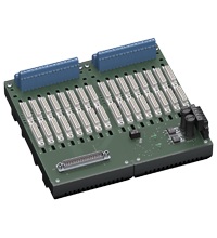
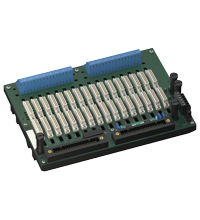
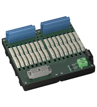
This device mounts on a HiC termination board.
Product Documentation: HiC2822
| Safety and Security Documentation | Language | File Type | File Size |
|---|---|---|---|
| Instruction manual | ENG | 168 KB | |
| Functional Safety Manual | ENG | 771 KB | |
| Manuals | |||
| System Manual | ENG | 5438 KB | |
Design / Simulation: HiC2822
| CAD | Language | File Type | File Size |
|---|---|---|---|
| CAD 3-D / CAD 3-D | ALL | STP | 2770 KB |
| CAD Portal / CAD Portal | ALL | LINK | --- |
| CAE | |||
| EPLAN macros H-System devices (EMA) / EPLAN-Makros Geräte H-System (EMA) | ALL | ZIP | 3536 KB |
Approvals: HiC2822
Associated Products: HiC2822
| Accessory of | ||||||
|---|---|---|---|---|---|---|
|
||||||
|
||||||
|
||||||


Choose from various selection criteria like safety integrity level, performance level, device function, and signal type and find the SIL/PL assessed device that you are looking for.


Pepperl+Fuchs SE
Lilienthalstraße 200
68307 Mannheim
Germany
info@de.pepperl-fuchs.com
 +49 621 776-0
Pepperl+Fuchs is a leading developer and manufacturer of electronic sensors and components for the global automation market. Continuous innovation, enduring quality, and steady growth have been the foundation of our success for more than 70 years. Pepperl+Fuchs employs 6,300 people worldwide and has manufacturing facilities in Germany, USA, Singapore, Hungary, Indonesia and Vietnam, most of them ISO 9001 certified.