

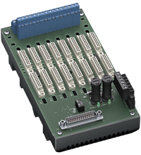
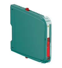
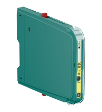
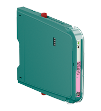
Termination Board HiCTB08-FBM-RAC-SC-IO08
- System board for Schneider, Foxboro FBM series
- For 8 modules
- For 8-channel cards FBM201/214(b)/216(b) (AI), FBM215/218/237 (AO), FBM204/205 (AO/AI), FBM244 (AI/AO), FBM247/248 (UIO)
- 24 V DC supply
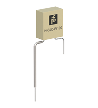
- Recommended modules: HiC2025(A) (AI), HiC2025ES (AI), HiC2031 (AO), HiC2081 (TI), HiC2831R5 (DI), HiC2883 (DO), HiC2441 (UIO)
- Hazardous area: screw terminals, blue
- Non-hazardous area: Sub-D connector (male), 25-pin


Please note: All product-related documents, such as certificates, declarations of conformity, etc., which were issued prior to the conversion under the name Pepperl+Fuchs GmbH or Pepperl+Fuchs AG, also apply to Pepperl+Fuchs SE.
Download the complete datasheet as a PDF:
Datasheet excerpt: Technical data of HiCTB08-FBM-RAC-SC-IO08
| Supply | ||
|---|---|---|
| Connection | X20: terminals 3, 5(+); 4, 6(-) | |
| Nominal voltage | 24 V DC , in consideration of rated voltage of used isolators | |
| Voltage drop | 0.9 V , voltage drop across the series diode on the termination board must be considered | |
| Ripple | ≤ 10 % | |
| Fusing | 2 A , in each case for 8 modules | |
| Power dissipation | ≤ 500 mW , without modules | |
| Reverse polarity protection | yes | |
| Redundancy | ||
| Supply | Redundancy available. The supply for the isolators is decoupled, monitored and fused. | |
| Fault indication output | ||
| Connection | X20: terminals 1, 2 | |
| Output type | volt-free contact | |
| Switch behaviour | no fault: relay contact closed power supply fault: relay contact open module fault: relay contact open |
|
| Contact loading | 30 V DC, 1 A | |
| Indicators/settings | ||
| Display elements | LED PWR1 (termination board power supply), green LED LED PWR2 (termination board power supply), green LED LED FAULT (fault indication), red LED - LED lits: module fault - LED flashes: power supply fault |
|
| Directive conformity | ||
| Electromagnetic compatibility | ||
| Directive 2014/30/EU | EN 61326-1:2013 (industrial locations) | |
| Conformity | ||
| Electromagnetic compatibility | NE 21:2017 For further information see system description. |
|
| Degree of protection | IEC 60529:2001 | |
| Ambient conditions | ||
| Ambient temperature | -20 ... 60 °C (-4 ... 140 °F) | |
| Storage temperature | -40 ... 70 °C (-40 ... 158 °F) | |
| Mechanical specifications | ||
| Degree of protection | IP20 | |
| Connection | ||
| Field side | explosion hazardous area: 4 screw terminals per module , blue | |
| Control side | non-explosion hazardous area: Sub-D connector , 25-pin | |
| Supply | pluggable screw terminals , black | |
| Fault output | pluggable screw terminals , black | |
| Core cross section | screw terminals: 0.25 ... 1.5 mm2 (24 ... 12 AWG) | |
| Material | housing: polycarbonate, 10 % glass fiber reinforced | |
| Mass | approx. 380 g | |
| Dimensions | 108 x 200 x 163 mm (4.25 x 7.9 x 6.42 inch) (W x H x D) , depth including module assembly | |
| Height | 200 mm | |
| Width | 108 mm | |
| Depth | 163 mm | |
| Mounting | on 35 mm DIN mounting rail acc. to EN 60715:2001 | |
| Data for application in connection with hazardous areas | ||
| EU-type examination certificate | CESI 06 ATEX 022 | |
| Marking |  II (1)G [Ex ia Ga] IIC II (1)D [Ex ia Da] IIIC I (M1) [Ex ia Ma] I II (1)G [Ex ia Ga] IIC II (1)D [Ex ia Da] IIIC I (M1) [Ex ia Ma] I |
|
| Non-hazardous area | ||
| Maximum safe voltage | 250 V (Attention! Um is no rated voltage.) | |
| Galvanic isolation | ||
| Field circuit/control circuit | safe electrical isolation acc. to IEC/EN 60079-11, voltage peak value 375 V | |
| Directive conformity | ||
| Directive 2014/34/EU | EN IEC 60079-0:2018+AC:2020 , EN 60079-11:2012 , EN 50303:2000 | |
| International approvals | ||
| UL approval | E106378 | |
| Control drawing | 116-0327 | |
| IECEx approval | ||
| IECEx certificate | IECEx CES 06.0003 | |
| IECEx marking | [Ex ia Ga] IIC [Ex ia Da] IIIC [Ex ia Ma] I |
|
| General information | ||
| Supplementary information | Observe the certificates, declarations of conformity, instruction manuals, and manuals where applicable. For information see www.pepperl-fuchs.com. | |
Classifications
| System | Classcode |
|---|---|
| ECLASS 13.0 | 27211016 |
| ECLASS 12.0 | 27211016 |
| ECLASS 11.0 | 27211016 |
| ECLASS 10.0.1 | 27219001 |
| ECLASS 9.0 | 27219001 |
| ECLASS 8.0 | 27219001 |
| ECLASS 5.1 | 27219901 |
| ETIM 9.0 | EC001485 |
| ETIM 8.0 | EC001485 |
| ETIM 7.0 | EC001485 |
| ETIM 6.0 | EC001485 |
| ETIM 5.0 | EC002653 |
| UNSPSC 12.1 | 39121018 |
Details: HiCTB08-FBM-RAC-SC-IO08
Function
The function of the termination board and the connector pin assignment are exactly fitted to the requirements of the Foxboro FBM system.
The signal is output to the process control system via the system connector.
Information about a missing supply voltage of the isolated barriers is available for the system as a volt-free contact.
Wiring errors from field side will be reported via the same relay contact, if this function is supported by the isolators.
The termination board has a robust glass fiber reinforced plastic housing.
The termination board is mounted in the switch cabinet on a 35 mm DIN mounting rail according to EN 60175.
Product Documentation: HiCTB08-FBM-RAC-SC-IO08
| Product information | Language | File Type | File Size |
|---|---|---|---|
| Pinout Table | ENG | 134 KB | |
| Brief Instructions | |||
| Brief instructions | ENG | 2805 KB | |
| Safety and Security Documentation | |||
| Instruction manual | ENG | 161 KB | |
| Manuals | |||
| System Manual | ENG | 5438 KB | |
Design / Simulation: HiCTB08-FBM-RAC-SC-IO08
| CAD | Language | File Type | File Size |
|---|---|---|---|
| CAD 2-D / CAD 2-D | ALL | ZIP | 16364 KB |
Approvals: HiCTB08-FBM-RAC-SC-IO08
| Certificates | Certificate No. | Language | File Type | File Size |
|---|---|---|---|---|
| Brasil TUV Rheinland Brazil | TÜV 14.0084 X | ALL | 1284 KB | |
| CESI IECEx Certificate of Conformity | IECEx CES 06.0003 | ALL | LINK | --- |
| China SITIIAS CCC Ex Certificate | 2021322308004238 (Singapore) | ALL | 1842 KB | |
| EU ATEX Category 3 G | PF23CERT7218X | ALL | 105 KB | |
| Europe CESI ATEX Category (1) GD ATEX Category (M1) | CESI 06 ATEX 022 | ALL | 869 KB | |
| India PESO (India) CCOE | A/P/HQ/KA/104/5881 (P508977) | ALL | 100 KB | |
| USA Canada UL Hazardous Location Certificate of Compliance cULus UL E106378 | CoC E106378 RepRef E106378-20100930 | ALL | 478 KB | |
| Control Drawings | ||||
| Control drawing UL / Control drawing UL | ALL | 166 KB | ||
| Declaration of Conformity | ||||
| EU Declaration of Conformity (P+F) / EU-Konformitäterklärung (P+F) | DOC-4098A | ALL | 50 KB | |
Associated Products: HiCTB08-FBM-RAC-SC-IO08
| Accessories | ||||||
|---|---|---|---|---|---|---|
|
||||||
|
||||||
|
||||||
|
||||||
|
||||||
|
||||||
|
||||||
|
||||||


Pepperl+Fuchs SE
Lilienthalstraße 200
68307 Mannheim
Germany
info@de.pepperl-fuchs.com
 +49 621 776-0
Pepperl+Fuchs is a leading developer and manufacturer of electronic sensors and components for the global automation market. Continuous innovation, enduring quality, and steady growth have been the foundation of our success for more than 70 years. Pepperl+Fuchs employs 6,300 people worldwide and has manufacturing facilities in Germany, USA, Singapore, Hungary, Indonesia and Vietnam, most of them ISO 9001 certified.