

Not available for purchase
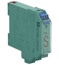
Switch Amplifier KFD2-SH-Ex1.T
- 1-channel isolated barrier
- 24 V DC supply
- Input for approved dry contacts or SN/S1N sensors
- Active voltage output
- Relay contact output
- Fault indication output
- Line fault detection (LFD)
- Up to SIL 3 acc. to IEC/EN 61508
- Up to PL d acc. to EN/ISO 13849


Please note: All product-related documents, such as certificates, declarations of conformity, etc., which were issued prior to the conversion under the name Pepperl+Fuchs GmbH or Pepperl+Fuchs AG, also apply to Pepperl+Fuchs SE.
Download the complete datasheet as a PDF:
Datasheet excerpt: Technical data of KFD2-SH-Ex1.T
| General specifications | ||
|---|---|---|
| Signal type | Digital Input | |
| Functional safety related parameters | ||
| Safety Integrity Level (SIL) | SIL 3 | |
| Performance level (PL) | PL d | |
| Supply | ||
| Connection | terminals 14, 15 | |
| Rated voltage | 20 ... 30 V DC | |
| Ripple | ≤ 10 % | |
| Rated current | ≤ 100 mA | |
| Power dissipation | 1.5 W | |
| Power consumption | max. 1.7 W | |
| Input | ||
| Connection side | field side | |
| Connection | terminals 4+, 6- | |
| Open circuit voltage/short-circuit current | approx. 8.4 V DC / approx. 11.7 mA | |
| Lead resistance | max. 50 Ω , cable capacitances and inductances must be observed in hazardous areas | |
| Switching point | ||
| Relay de-energized | I < 2.1 mA and I > 5.9 mA , output switched off | |
| Relay energized | 2.8 mA < I < 5.3 mA , output switched on | |
| Response delay | ≤ 1 ms | |
| Output | ||
| Connection side | control side | |
| Connection | output I: terminals 7+, 8- ; output II: terminals 9, 10 ; output III: terminals 11, 12 | |
| Output I | active voltage output, short-circuit proof 0-signal: 0 V 1-signal: 20 ... 31 V DC at max. 15 mA fault: 0 V |
|
| Output II | relay | |
| Contact loading | 48 V AC/DC 250 mA |
|
| Mechanical life | ≤ 20 x 106 switching cycles | |
| Output III | relay , fault signal | |
| Contact loading | 48 V AC/DC 250 mA |
|
| Mechanical life | ≤ 20 x 106 switching cycles | |
| Transfer characteristics | ||
| Switching frequency | ||
| Output I | ≤ 50 Hz | |
| Output II | ≤ 5 Hz | |
| Output III | ≤ 5 Hz | |
| Indicators/settings | ||
| Display elements | LEDs | |
| Labeling | space for labeling at the front | |
| Directive conformity | ||
| Electromagnetic compatibility | ||
| Directive 2014/30/EU | EN 61326-1:2013 (industrial locations) | |
| Machinery Directive | ||
| Directive 2006/42/EC | EN/ISO 13849-1:2015 | |
| Conformity | ||
| Electromagnetic compatibility | NE 21:2011 | |
| Degree of protection | IEC 60529:2001 | |
| Safety | IEC/EN 61508:2010 | |
| Ambient conditions | ||
| Ambient temperature | -20 ... 60 °C (-4 ... 140 °F) | |
| Mechanical specifications | ||
| Degree of protection | IP20 | |
| Connection | screw terminals | |
| Mass | approx. 150 g | |
| Dimensions | 20 x 119 x 115 mm (0.8 x 4.7 x 4.5 inch) (W x H x D) , housing type B2 | |
| Height | 119 mm | |
| Width | 20 mm | |
| Depth | 115 mm | |
| Mounting | on 35 mm DIN mounting rail acc. to EN 60715:2001 | |
| Data for application in connection with hazardous areas | ||
| EU-type examination certificate | PTB 00 ATEX 2041 | |
| Marking |  II (1)GD [Ex ia] IIC [circuit(s) in zone 0/1/2] II (1)GD [Ex ia] IIC [circuit(s) in zone 0/1/2] |
|
| Input | EEx ia IIC | |
| Voltage | 9.56 V | |
| Current | 16.8 mA | |
| Power | 41 mW (linear characteristic) | |
| Supply | ||
| Maximum safe voltage | 40 V AC/DC (Attention! The rated voltage can be lower.) | |
| Output | ||
| Contact loading | 48 V AC/DC 250 mA |
|
| Maximum safe voltage | 60 V AC/DC (Attention! The rated voltage can be lower.) | |
| Certificate | TÜV 99 ATEX 1493 X | |
| Marking | II 3G Ex nA nC IIC T4 |
|
| Galvanic isolation | ||
| Input/Output | safe electrical isolation acc. to IEC/EN 60079-11, voltage peak value 375 V | |
| Input/power supply | safe electrical isolation acc. to IEC/EN 60079-11, voltage peak value 375 V | |
| Directive conformity | ||
| Directive 2014/34/EU | EN 60079-0:2012+A11:2013 , EN 60079-11:2012 , EN 60079-15:2010 | |
| International approvals | ||
| IECEx approval | ||
| IECEx certificate | IECEx TUN 19.0013X | |
| IECEx marking | Ex ec nC IIC T4 Gc | |
| General information | ||
| Supplementary information | Observe the certificates, declarations of conformity, instruction manuals, and manuals where applicable. For information see www.pepperl-fuchs.com. | |
Classifications
| System | Classcode |
|---|---|
| ECLASS 13.0 | 27210121 |
| ECLASS 12.0 | 27210121 |
| ECLASS 11.0 | 27210121 |
| ECLASS 10.0.1 | 27210121 |
| ECLASS 9.0 | 27210121 |
| ECLASS 8.0 | 27210121 |
| ECLASS 5.1 | 27210121 |
| ETIM 9.0 | EC001485 |
| ETIM 8.0 | EC001485 |
| ETIM 7.0 | EC001485 |
| ETIM 6.0 | EC001485 |
| ETIM 5.0 | EC001485 |
| UNSPSC 12.1 | 32101514 |
Details: KFD2-SH-Ex1.T
Function
This isolated barrier is used for intrinsic safety applications.
The device transfers digital signals (SN/S1N proximity sensors or approved dry contacts) from a hazardous area to a safe area.
The input controls one active voltage output and one relay contact output with a NO contact.
Unlike an SN/S1N series proximity sensor, a mechanical contact requires a 10 kΩ resistor to be placed across the contact in addition to a 1.5 kΩ resistor in series.
Lead breakage (LB) and short circuit (SC) conditions of the control circuit are continuously monitored.
During an fault condition, the fault indication output and the outputs I and II de-energize.
For safety applications up to SIL3, output I must be used. For safety applications up to SIL2, output I and output II can be used.
Product Documentation: KFD2-SH-Ex1.T
| Safety and Security Documentation | Language | File Type | File Size |
|---|---|---|---|
| Instruction manual | ENG | 149 KB | |
| Original Instructions/Functional Safety Manual | ENG | 660 KB | |
| Manuals | |||
| Manual | ENG | 3685 KB | |
Design / Simulation: KFD2-SH-Ex1.T
| CAD | Language | File Type | File Size |
|---|---|---|---|
| CAD 3-D / CAD 3-D | ALL | STP | 2510 KB |
Approvals: KFD2-SH-Ex1.T
| Certificates | Certificate No. | Language | File Type | File Size |
|---|---|---|---|---|
| Europe PTB ATEX Category (1) GD | PTB 00 ATEX 2041 | ALL | 422 KB | |
| Worldwide TÜV SÜD Functional Safety Assessment | PM85769T | ALL | 797 KB | |
| Declaration of Conformity | ||||
| EU Declaration of Conformity (P+F) / EU-Konformitäterklärung (P+F) | DOC-0594B | ALL | 81 KB | |
Associated Products: KFD2-SH-Ex1.T
| Matching System Components | ||||||
|---|---|---|---|---|---|---|
|
||||||
|
||||||
|
||||||
|
||||||
|
||||||
|
||||||
| Accessories | ||||||
|
||||||
|
||||||
|
||||||


Choose from various selection criteria like safety integrity level, performance level, device function, and signal type and find the SIL/PL assessed device that you are looking for.


Pepperl+Fuchs SE
Lilienthalstraße 200
68307 Mannheim
Germany
info@de.pepperl-fuchs.com
 +49 621 776-0
Pepperl+Fuchs is a leading developer and manufacturer of electronic sensors and components for the global automation market. Continuous innovation, enduring quality, and steady growth have been the foundation of our success for more than 70 years. Pepperl+Fuchs employs 6,300 people worldwide and has manufacturing facilities in Germany, USA, Singapore, Hungary, Indonesia and Vietnam, most of them ISO 9001 certified.