

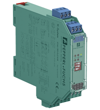
Switch Amplifier KFA6-SR2-Ex2.W.IR
- 2-channel isolated barrier
- 230 V AC supply
- Dry contact or NAMUR inputs
- Latching relay contact output
- Line fault detection (LFD)


Please note: All product-related documents, such as certificates, declarations of conformity, etc., which were issued prior to the conversion under the name Pepperl+Fuchs GmbH or Pepperl+Fuchs AG, also apply to Pepperl+Fuchs SE.
Download the complete datasheet as a PDF:
Datasheet excerpt: Technical data of KFA6-SR2-Ex2.W.IR
| General specifications | ||
|---|---|---|
| Signal type | Digital Input | |
| Supply | ||
| Connection | terminals 14, 15 | |
| Rated voltage | 207 ... 253 V AC, 45 ... 65 Hz | |
| Power consumption | max. 1.5 W | |
| Input | ||
| Connection side | field side | |
| Connection | terminals 1+, 2+, 3-; 4+, 5+, 6- | |
| Rated values | acc. to EN 60947-5-6 (NAMUR) | |
| Open circuit voltage/short-circuit current | approx. 8 V DC / approx. 8 mA | |
| Line fault detection | breakage I ≤ 0.1 mA , short-circuit I > 6 mA | |
| Pulse/Pause ratio | min. 10 ms / min. 10 ms | |
| Output | ||
| Connection side | control side | |
| Connection | output I: terminals 7, 8, 9 ; output II: terminals 10, 11, 12 | |
| Output I, II | signal ; relay | |
| Contact loading | 253 V AC/2 A/cos φ > 0.7; 126.5 V AC/4 A/cos φ > 0.7; 40 V DC/2 A resistive load | |
| Energized/De-energized delay | approx. 20 ms / approx. 20 ms | |
| Mechanical life | 107 switching cycles | |
| Transfer characteristics | ||
| Switching frequency | ≤ 10 Hz | |
| Galvanic isolation | ||
| Input/Output | reinforced insulation according to IEC/EN 61010-1, rated insulation voltage 300 Veff | |
| Input/power supply | reinforced insulation according to IEC/EN 61010-1, rated insulation voltage 300 Veff | |
| Output/power supply | reinforced insulation according to IEC/EN 61010-1, rated insulation voltage 300 Veff | |
| Output/Output | reinforced insulation according to IEC/EN 61010-1, rated insulation voltage 300 Veff | |
| Indicators/settings | ||
| Display elements | LEDs | |
| Labeling | space for labeling at the front | |
| Directive conformity | ||
| Electromagnetic compatibility | ||
| Directive 2014/30/EU | EN 61326-1:2013 (industrial locations) | |
| Low voltage | ||
| Directive 2014/35/EU | EN 61010-1:2010 | |
| Conformity | ||
| Electromagnetic compatibility | NE 21:2006 | |
| Degree of protection | IEC 60529:2001 | |
| Input | EN 60947-5-6:2000 | |
| Ambient conditions | ||
| Ambient temperature | -20 ... 60 °C (-4 ... 140 °F) | |
| Mechanical specifications | ||
| Degree of protection | IP20 | |
| Connection | screw terminals | |
| Mass | approx. 150 g | |
| Dimensions | 20 x 119 x 115 mm (0.8 x 4.7 x 4.5 inch) (W x H x D) , housing type B2 | |
| Height | 119 mm | |
| Width | 20 mm | |
| Depth | 115 mm | |
| Mounting | on 35 mm DIN mounting rail acc. to EN 60715:2001 | |
| Data for application in connection with hazardous areas | ||
| EU-type examination certificate | PTB 00 ATEX 2081 | |
| Marking |  II (1)G [Ex ia Ga] IIC II (1)D [Ex ia Da] IIIC I (M1) [Ex ia Ma] I II (1)G [Ex ia Ga] IIC II (1)D [Ex ia Da] IIIC I (M1) [Ex ia Ma] I |
|
| Input | Ex ia | |
| Voltage | 10.6 V | |
| Current | 19.1 mA | |
| Power | 51 mW (linear characteristic) | |
| Supply | ||
| Maximum safe voltage | 253 V AC (Attention! Um is no rated voltage.) | |
| Output | ||
| Contact loading | 253 V AC/2 A/cos φ > 0.7; 126.5 V AC/4 A/cos φ > 0.7; 40 V DC/2 A resistive load | |
| Maximum safe voltage | 253 V AC (Attention! The rated voltage can be lower.) | |
| Galvanic isolation | ||
| Input/input | not available | |
| Input/Output | safe electrical isolation acc. to IEC/EN 60079-11, voltage peak value 375 V | |
| Input/power supply | safe electrical isolation acc. to IEC/EN 60079-11, voltage peak value 375 V | |
| Directive conformity | ||
| Directive 2014/34/EU | EN IEC 60079-0:2018+AC:2020 , EN 60079-11:2012 | |
| International approvals | ||
| FM approval | ||
| Control drawing | 116-0035 | |
| UL approval | ||
| Control drawing | 116-0145 | |
| CSA approval | ||
| Control drawing | 116-0047 | |
| IECEx approval | ||
| IECEx certificate | IECEx PTB 11.0031 | |
| IECEx marking | [Ex ia Ga] IIC [Ex ia Da] IIIC [Ex ia Ma] I |
|
| General information | ||
| Supplementary information | Observe the certificates, declarations of conformity, instruction manuals, and manuals where applicable. For information see www.pepperl-fuchs.com. | |
Classifications
| System | Classcode |
|---|---|
| ECLASS 13.0 | 27210121 |
| ECLASS 12.0 | 27210121 |
| ECLASS 11.0 | 27210121 |
| ECLASS 10.0.1 | 27210121 |
| ECLASS 9.0 | 27210121 |
| ECLASS 8.0 | 27210121 |
| ECLASS 5.1 | 27210121 |
| ETIM 9.0 | EC001485 |
| ETIM 8.0 | EC001485 |
| ETIM 7.0 | EC001485 |
| ETIM 6.0 | EC001485 |
| ETIM 5.0 | EC001485 |
| UNSPSC 12.1 | 32101514 |
Details: KFA6-SR2-Ex2.W.IR
Function
This isolated barrier is used for intrinsic safety applications.
The device is used for level control, pump control and other switching applications.
The device transfers digital signals from NAMUR sensors or dry contacts from the hazardous area to the non-hazardous area.
The device is easily configured by the use of DIP switches.
A fault is signalized by LEDs.
Informative Literature: KFA6-SR2-Ex2.W.IR
| Literature | Language | File Type | File Size |
|---|---|---|---|
| Application Report - Biological Cleaning of Wastwater and Secondary Sedimentation Stage | ENG | 566 KB | |
| Application Report - Energy Generation in Wastwater Treatment Plants | ENG | 532 KB | |
| Application Report - Generating Electricity in Coal-Fired Power Plants | ENG | 412 KB | |
| Application Report - Sand Trap and Preliminary Sedimentation Stage | ENG | 448 KB | |
| Application Report - Screening Systems in Sewage Treatment Plants | ENG | 577 KB | |
| Application Report - Sicherer Brennstofftransport in Kohlekraftwerken | ENG | 391 KB | |
| Application Report - Water Inlet in Wastewater Treatment Plants | ENG | 526 KB |
Product Documentation: KFA6-SR2-Ex2.W.IR
| Safety and Security Documentation | Language | File Type | File Size |
|---|---|---|---|
| Instruction manual | ENG | 176 KB | |
| Manuals | |||
| Manual | ENG | 3685 KB | |
Design / Simulation: KFA6-SR2-Ex2.W.IR
| CAD | Language | File Type | File Size |
|---|---|---|---|
| CAD 3-D / CAD 3-D | ALL | STP | 2510 KB |
| CAD Portal / CAD Portal | ALL | LINK | --- |
| CAE | |||
| CAE EPLAN Data Portal / CAE EPLAN Data Portal | ALL | LINK | --- |
| CAE EPLAN macro EDZ / CAE EPLAN Makro EDZ | ALL | EDZ | 1511 KB |
Approvals: KFA6-SR2-Ex2.W.IR
| Certificates | Certificate No. | Language | File Type | File Size |
|---|---|---|---|---|
| South Africa MASC | MASC MS/17-0856 | ALL | 238 KB | |
| Australia SIMTARS | ANZEx 11.2009 | ALL | 318 KB | |
| Brasil TUV Rheinland Brazil | TÜV 13.1164 | ALL | 1141 KB | |
| Canada CSA | CoC 1029981 C | ALL | 177 KB | |
| Canada UL cUL | E106378 cUL (QUZW7) | ALL | LINK | --- |
| China SITIIAS CCC Ex Certificate | 2020322316001423 (Bintan) | ALL | 2017 KB | |
| DNV Marine | TAA00001WX | ALL | 114 KB | |
| Europe PTB ATEX Category (1) GD | PTB 00 ATEX 2081 | ALL | 1544 KB | |
| Korea KOSHA | 09-AV4BO-0224-1 | ALL | 350 KB | |
| PTB IECEx Certificate of Conformity | IECEx PTB 11.0031 | ALL | LINK | --- |
| USA Canada UL Hazardous Location Certificate of Compliance cULus UL E106378 | CoC 20160608 - E106378 RepRef 19970520 | ALL | 246 KB | |
| USA FM | FM 19 US 0207X | ALL | 350 KB | |
| USA UL | E106378 UL (QUZW) | ALL | LINK | --- |
| Ukraine SERTIS Ex | SC 21.0646 X | ALL | 12351 KB | |
| Control Drawings | ||||
| Control drawing UL / Control drawing UL | ALL | 165 KB | ||
| Control drawing FM / Control drawing FM | ALL | 130 KB | ||
| Control drawing CSA / Control drawing CSA | ALL | 159 KB | ||
| Declaration of Conformity | ||||
| EU Declaration of Conformity (P+F) / EU-Konformitäterklärung (P+F) | DOC-0636D | ALL | 56 KB | |
Associated Products: KFA6-SR2-Ex2.W.IR
| Matching System Components | ||||||
|---|---|---|---|---|---|---|
|
||||||
| Accessories | ||||||
|
||||||
|
||||||
|
||||||
|
||||||


Choose from various selection criteria like safety integrity level, performance level, device function, and signal type and find the SIL/PL assessed device that you are looking for.


Pepperl+Fuchs SE
Lilienthalstraße 200
68307 Mannheim
Germany
info@de.pepperl-fuchs.com
 +49 621 776-0
Pepperl+Fuchs is a leading developer and manufacturer of electronic sensors and components for the global automation market. Continuous innovation, enduring quality, and steady growth have been the foundation of our success for more than 70 years. Pepperl+Fuchs employs 6,300 people worldwide and has manufacturing facilities in Germany, USA, Singapore, Hungary, Indonesia and Vietnam, most of them ISO 9001 certified.