

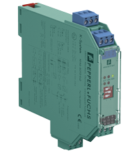
Switch Amplifier KFA6-SOT2-Ex2
- 2-channel isolated barrier
- 230 V AC supply
- Dry contact or NAMUR inputs
- Passive transistor output, non-polarized
- Line fault detection (LFD)
- Reversible mode of operation
- Up to SIL 2 acc. to IEC/EN 61508


Please note: All product-related documents, such as certificates, declarations of conformity, etc., which were issued prior to the conversion under the name Pepperl+Fuchs GmbH or Pepperl+Fuchs AG, also apply to Pepperl+Fuchs SE.
Download the complete datasheet as a PDF:
Datasheet excerpt: Technical data of KFA6-SOT2-Ex2
| General specifications | ||
|---|---|---|
| Signal type | Digital Input | |
| Functional safety related parameters | ||
| Safety Integrity Level (SIL) | SIL 2 | |
| Supply | ||
| Connection | terminals 14, 15 | |
| Rated voltage | 207 ... 253 V AC, 45 ... 65 Hz | |
| Power dissipation | 1 W | |
| Power consumption | max. 1.5 W | |
| Input | ||
| Connection side | field side | |
| Connection | terminals 1+, 2+, 3-; 4+, 5+, 6- | |
| Rated values | acc. to EN 60947-5-6 (NAMUR), see manual for electrical data | |
| Open circuit voltage/short-circuit current | approx. 8 V DC / approx. 8 mA | |
| Switching point/switching hysteresis | 1.2 ... 2.1 mA / approx. 0.2 mA | |
| Line fault detection | breakage I ≤ 0.1 mA , short-circuit I > 6 mA | |
| Output | ||
| Connection side | control side | |
| Connection | output I: terminals 7, 8 ; output II: terminals 8, 9 | |
| Switching voltage | max. 40 V | |
| Switching current | max. 100 mA , short-circuit protected | |
| Signal level | 1-signal: switching voltage - 2.5 V max. at 10 mA switching current or 3 V max. at 100 mA switching current 0-signal: switched off (off-state current ≤ 10 µA) |
|
| Output I, II | signal ; electronic output, passive | |
| Transfer characteristics | ||
| Switching frequency | ≤ 5 kHz | |
| Galvanic isolation | ||
| Input/Output | reinforced insulation according to IEC/EN 61010-1, rated insulation voltage 300 Veff | |
| Input/power supply | reinforced insulation according to IEC/EN 61010-1, rated insulation voltage 300 Veff | |
| Output/power supply | reinforced insulation according to IEC/EN 61010-1, rated insulation voltage 300 Veff | |
| Output/Output | not available | |
| Indicators/settings | ||
| Display elements | LEDs | |
| Control elements | DIP switch | |
| Configuration | via DIP switches | |
| Labeling | space for labeling at the front | |
| Directive conformity | ||
| Electromagnetic compatibility | ||
| Directive 2014/30/EU | EN 61326-1:2013 (industrial locations) | |
| Low voltage | ||
| Directive 2014/35/EU | EN 61010-1:2010 | |
| Conformity | ||
| Electromagnetic compatibility | NE 21:2012 | |
| Degree of protection | IEC 60529 | |
| Ambient conditions | ||
| Ambient temperature | -20 ... 60 °C (-4 ... 140 °F) | |
| Mechanical specifications | ||
| Degree of protection | IP20 | |
| Connection | screw terminals | |
| Mass | approx. 150 g | |
| Dimensions | 20 x 119 x 115 mm (0.8 x 4.7 x 4.5 inch) (W x H x D) , housing type B2 | |
| Height | 119 mm | |
| Width | 20 mm | |
| Depth | 115 mm | |
| Mounting | on 35 mm DIN mounting rail acc. to EN 60715:2001 | |
| Data for application in connection with hazardous areas | ||
| EU-type examination certificate | PTB 98 ATEX 2164 | |
| Marking |  II (1) G [Ex ia] IIC II (1) D [Ex ia] IIIC II (1) G [Ex ia] IIC II (1) D [Ex ia] IIIC |
|
| Input | Ex ia IIC, Ex ia IIIC | |
| Voltage | 10.5 V | |
| Current | 13 mA | |
| Power | 34 mW (linear characteristic) | |
| Supply | ||
| Maximum safe voltage | 253 V AC (Attention! Um is no rated voltage.) | |
| Output | ||
| Maximum safe voltage | 253 V AC (Attention! The rated voltage can be lower.) | |
| Galvanic isolation | ||
| Input/input | not available | |
| Input/Output | safe electrical isolation acc. to IEC/EN 60079-11, voltage peak value 375 V | |
| Input/power supply | safe electrical isolation acc. to IEC/EN 60079-11, voltage peak value 375 V | |
| Directive conformity | ||
| Directive 2014/34/EU | EN 60079-0:2012+A11:2013 , EN 60079-11:2012 | |
| International approvals | ||
| UL approval | ||
| Control drawing | 116-0145 | |
| CSA approval | ||
| Control drawing | 116-0047 | |
| General information | ||
| Supplementary information | Observe the certificates, declarations of conformity, instruction manuals, and manuals where applicable. For information see www.pepperl-fuchs.com. | |
Classifications
| System | Classcode |
|---|---|
| ECLASS 13.0 | 27210121 |
| ECLASS 12.0 | 27210121 |
| ECLASS 11.0 | 27210121 |
| ECLASS 10.0.1 | 27210121 |
| ECLASS 9.0 | 27210121 |
| ECLASS 8.0 | 27210121 |
| ECLASS 5.1 | 27210121 |
| ETIM 9.0 | EC001485 |
| ETIM 8.0 | EC001485 |
| ETIM 7.0 | EC001485 |
| ETIM 6.0 | EC001485 |
| ETIM 5.0 | EC001485 |
| UNSPSC 12.1 | 32101514 |
Details: KFA6-SOT2-Ex2
Function
This isolated barrier is used for intrinsic safety applications. It transfers digital signals (NAMUR sensors/mechanical contacts) from a hazardous area to a safe area.
Each proximity sensor or switch controls a passive transistor output for the safe area load. The normal output state can be reversed using switch S1 for channel I and switch S2 for channel II. Switch S3 enables or disables line fault detection of the field circuit.
During an error condition, the transistors revert to their de-energized state and LEDs indicate the fault according to NAMUR NE44.
Informative Literature: KFA6-SOT2-Ex2
| Literature | Language | File Type | File Size |
|---|---|---|---|
| Application Report - Biological Cleaning of Wastwater and Secondary Sedimentation Stage | ENG | 566 KB | |
| Application Report - Energy Generation in Wastwater Treatment Plants | ENG | 532 KB | |
| Application Report - Generating Electricity in Coal-Fired Power Plants | ENG | 412 KB | |
| Application Report - Sand Trap and Preliminary Sedimentation Stage | ENG | 448 KB | |
| Application Report - Screening Systems in Sewage Treatment Plants | ENG | 577 KB | |
| Application Report - Sicherer Brennstofftransport in Kohlekraftwerken | ENG | 391 KB | |
| Application Report - Water Inlet in Wastewater Treatment Plants | ENG | 526 KB |
Product Documentation: KFA6-SOT2-Ex2
| Safety and Security Documentation | Language | File Type | File Size |
|---|---|---|---|
| Instruction manual | ENG | 49 KB | |
| Manuals | |||
| Manual | ENG | 3685 KB | |
Design / Simulation: KFA6-SOT2-Ex2
| CAD | Language | File Type | File Size |
|---|---|---|---|
| CAD 3-D / CAD 3-D | ALL | STP | 2308 KB |
| CAD Portal / CAD Portal | ALL | LINK | --- |
| CAE | |||
| CAE EPLAN Data Portal / CAE EPLAN Data Portal | ALL | LINK | --- |
| CAE EPLAN macro EDZ / CAE EPLAN Makro EDZ | ALL | EDZ | 1376 KB |
Approvals: KFA6-SOT2-Ex2
| Certificates | Certificate No. | Language | File Type | File Size |
|---|---|---|---|---|
| Canada CSA | CoC 1029981 C | ALL | 177 KB | |
| Canada UL cUL | E106378 cUL (QUZW7) | ALL | LINK | --- |
| Europe PTB ATEX Category (1) GD | PTB 98 ATEX 2164 | ALL | 816 KB | |
| Japan TIIS | TC16172 | ALL | 2037 KB | |
| Korea KOSHA | 15-AV4BO-0432 | ALL | 310 KB | |
| USA Canada UL Hazardous Location Certificate of Compliance cULus UL E106378 | CoC 20160608 - E106378 RepRef 19970520 | ALL | 246 KB | |
| USA UL | E106378 UL (QUZW) | ALL | LINK | --- |
| exida Functional Safety Assessment | P+F 01/09-02D R002 | ALL | 154 KB | |
| Control Drawings | ||||
| Control drawing UL / Control drawing UL | ALL | 165 KB | ||
| Control drawing CSA / Control drawing CSA | ALL | 159 KB | ||
| Declaration of Conformity | ||||
| EU Declaration of Conformity (P+F) / EU-Konformitäterklärung (P+F) | DOC-0974A | ALL | 52 KB | |
Associated Products: KFA6-SOT2-Ex2
| Matching System Components | ||||||
|---|---|---|---|---|---|---|
|
||||||
| Accessories | ||||||
|
||||||
|
||||||
|
||||||
|
||||||


Choose from various selection criteria like safety integrity level, performance level, device function, and signal type and find the SIL/PL assessed device that you are looking for.


Pepperl+Fuchs SE
Lilienthalstraße 200
68307 Mannheim
Germany
info@de.pepperl-fuchs.com
 +49 621 776-0
Pepperl+Fuchs is a leading developer and manufacturer of electronic sensors and components for the global automation market. Continuous innovation, enduring quality, and steady growth have been the foundation of our success for more than 70 years. Pepperl+Fuchs employs 6,300 people worldwide and has manufacturing facilities in Germany, USA, Singapore, Hungary, Indonesia and Vietnam, most of them ISO 9001 certified.