

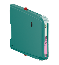
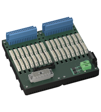
SMART Transmitter Power Supply HiC2025ES
- 1-channel isolated barrier
- 24 V DC supply (bus powered)
- Input for 2-wire SMART transmitters and current sources
- Output for 4 mA ... 20 mA or 1 V ... 5 V
- Sink or source mode
- Line fault detection (LFD)
- Up to SIL 3 acc. to IEC/EN 61508


Please note: All product-related documents, such as certificates, declarations of conformity, etc., which were issued prior to the conversion under the name Pepperl+Fuchs GmbH or Pepperl+Fuchs AG, also apply to Pepperl+Fuchs SE.
Download the complete datasheet as a PDF:
Datasheet excerpt: Technical data of HiC2025ES
| General specifications | ||
|---|---|---|
| Signal type | Analog input | |
| Functional safety related parameters | ||
| Safety Integrity Level (SIL) | SIL 3 | |
| Systematic capability (SC) | SC 3 | |
| Supply | ||
| Connection | SL1: 1a(-), 1b(-); 2a(+), 2b(+) | |
| Rated voltage | 19 ... 30 V DC bus powered via Termination Board | |
| Ripple | ≤ 10 % | |
| Rated current | ≤ 50 mA | |
| Power dissipation | ≤ 800 mW | |
| Power consumption | ≤ 1.2 W | |
| Input | ||
| Connection side | field side | |
| Connection | SL2: 5a(+), 1b(-); 5a(+), 5b(-) | |
| Input signal | 4 ... 20 mA , limited to approx. 27 mA reverse polarity protected | |
| Line fault detection | downscaling ≤ 3 mA ; upscaling ≥ 22 mA | |
| Voltage drop | approx. 5 V on SL2: 5a(+), 1b(-) | |
| Available voltage | ≥ 15 V at 20 mA on SL2: 5a(+), 5b(-) | |
| Output | ||
| Connection side | control side | |
| Connection | SL1: 8a(+), 7a(-) | |
| Load | 0 ... 300 Ω (source mode) | |
| Output signal | source mode: 4 ... 20 mA or 1 ... 5 V (internal resistor: 250 Ω, 0.1 %) sink mode: 4 ... 20 mA, operating voltage 16 ... 28 V For additional internal or external loads the voltage drop has to be considered, e. g. 250 Ω x 20 mA = 5 V. |
|
| Ripple | 20 mV rms | |
| Fault indication output | ||
| Connection | SL1: 6b | |
| Output type | open collector transistor (internal fault bus) | |
| Transfer characteristics | ||
| Deviation | at 20 °C (68 °F) ≤ ± 20 µA incl. calibration, linearity, hysteresis, loads and supply voltage fluctuations (source mode and sink mode 4 ... 20 mA) ≤ 10 mV incl. calibration, linearity, hysteresis and fluctuations of supply voltage (source mode 1 ... 5 V) |
|
| Influence of ambient temperature | < 2 µA/K (0 ... 70 °C (32 ... 158 °F)); < 4 µA/K (-20 ... 0 °C (-4 ... 32 °F)) (source mode and sink mode 4 ... 20 mA) < 0.5 mV/K (0 ... 70 °C (32 ... 158 °F)); < 1 mV/K (-20 ... 0 °C (-4 ... 32 °F)) (source mode 1 ... 5 V) |
|
| Frequency range | field side into the control side: bandwidth with 1 mApp signal 0 ... 3 kHz (-3 dB) control side into the field side: bandwidth with 0.5 Vpp signal 0 ... 3 kHz (-3 dB) |
|
| Settling time | ≤ 200 ms | |
| Rise time/fall time | ≤ 20 ms | |
| Galvanic isolation | ||
| Input/Output | safe electrical isolation acc. to IEC/EN 60079-11, voltage peak value 375 V | |
| Input/power supply | safe electrical isolation acc. to IEC/EN 60079-11, voltage peak value 375 V | |
| Output/power supply | Basic isolation acc. to EN 61010-1 rated insulation voltage ≤ 50 V | |
| Indicators/settings | ||
| Display elements | LEDs | |
| Control elements | DIP switch | |
| Factory setting | output: current source | |
| Configuration | via DIP switches | |
| Labeling | space for labeling at the front | |
| Directive conformity | ||
| Electromagnetic compatibility | ||
| Directive 2014/30/EU | EN 61326-1:2013 (industrial locations) | |
| Conformity | ||
| Electromagnetic compatibility | NE 21:2017 For further information see system description. |
|
| Degree of protection | IEC 60529:2001 | |
| Ambient conditions | ||
| Ambient temperature | -20 ... 70 °C (-4 ... 158 °F) | |
| Mechanical specifications | ||
| Degree of protection | IP20 | |
| Mass | approx. 100 g | |
| Dimensions | 12.5 x 106 x 128 mm (0.5 x 4.2 x 5.1 inch) (W x H x D) | |
| Height | 106 mm | |
| Width | 12.5 mm | |
| Depth | 128 mm | |
| Mounting | on termination board | |
| Coding | pin 1 and 3 trimmed For further information see system description. |
|
| Data for application in connection with hazardous areas | ||
| EU-type examination certificate | CESI 10 ATEX 063 | |
| Marking |  II (1)G [Ex ia Ga] IIC II (1)D [Ex ia Da] IIIC I (M1) [Ex ia Ma] I II (1)G [Ex ia Ga] IIC II (1)D [Ex ia Da] IIIC I (M1) [Ex ia Ma] I |
|
| Input | Ex ia | |
| Supply | ||
| Maximum safe voltage | 253 V AC (Attention! Um is no rated voltage.) | |
| Equipment | SL2: 5a(+), 5b(-) | |
| Voltage | 25.2 V | |
| Current | 100 mA | |
| Power | 630 mW | |
| Internal capacitance | 5.7 nF | |
| Internal inductance | negligible | |
| Equipment | SL2: 5a(+), 1b(-) | |
| Voltage | < 30 V | |
| Current | < 128 mA | |
| Voltage | 7.2 V | |
| Current | 100 mA | |
| Power | 25 mW | |
| Internal capacitance | 5.7 nF | |
| Internal inductance | negligible | |
| Certificate | CESI 19 ATEX 016 X | |
| Marking | II 3G Ex ec IIC T4 Gc |
|
| Directive conformity | ||
| Directive 2014/34/EU | EN 60079-0:2012+A11:2013 , EN 60079-11:2012 , EN 60079-7:2015 | |
| International approvals | ||
| UL approval | E106378 | |
| Control drawing | 116-0376 (cULus) | |
| IECEx approval | ||
| IECEx certificate | IECEx CES 10.0021X | |
| IECEx marking | [Ex ia Ga] IIC , [Ex ia Da] IIIC , [Ex ia Ma] I Ex ec IIC T4 Gc |
|
| General information | ||
| Supplementary information | Observe the certificates, declarations of conformity, instruction manuals, and manuals where applicable. For information see www.pepperl-fuchs.com. | |
Classifications
| System | Classcode |
|---|---|
| ECLASS 13.0 | 27210119 |
| ECLASS 12.0 | 27210119 |
| ECLASS 11.0 | 27210119 |
| ECLASS 10.0.1 | 27210119 |
| ECLASS 9.0 | 27210119 |
| ECLASS 8.0 | 27210119 |
| ECLASS 5.1 | 27210119 |
| ETIM 9.0 | EC001485 |
| ETIM 8.0 | EC001485 |
| ETIM 7.0 | EC001485 |
| ETIM 6.0 | EC001485 |
| ETIM 5.0 | EC001485 |
| UNSPSC 12.1 | 32101514 |
Details: HiC2025ES
Function
This isolated barrier is used for intrinsic safety applications.
The device supplies 2-wire transmitters in the hazardous area, and can also be used with current sources.
The device transfers the analog input signal to the non-hazardous area as an isolated current value.
Bi-directional communication is supported for SMART transmitters that use current modulation to transmit data and voltage modulation to receive data.
The output is selected as a current source, current sink, or voltage source via DIP switches.
A separate fault output on the bus is signaled, if the input signal is outside the range of 3 mA ... 22 mA.
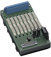
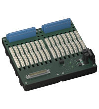
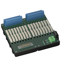
This device mounts on a HiC termination board.
Product Documentation: HiC2025ES
| Safety and Security Documentation | Language | File Type | File Size |
|---|---|---|---|
| Instruction manual | ENG | 167 KB | |
| Safety Manual | ENG | 427 KB | |
| Manuals | |||
| System Manual | ENG | 5438 KB | |
Design / Simulation: HiC2025ES
| CAD | Language | File Type | File Size |
|---|---|---|---|
| CAD 3-D / CAD 3-D | ALL | STP | 2770 KB |
| CAD Portal / CAD Portal | ALL | LINK | --- |
Approvals: HiC2025ES
| Certificates | Certificate No. | Language | File Type | File Size |
|---|---|---|---|---|
| CESI IECEx Certificate of Conformity | IECEx CES 10.0021X | ALL | LINK | --- |
| China SITIIAS CCC Ex Certificate | 2021322316003614 (Singapore) | ALL | 1095 KB | |
| Europe CESI ATEX Category (1) D ATEX Category (M1) ATEX Category (1) G | CESI 10 ATEX 063 | ALL | 661 KB | |
| Europe CESI ATEX Category 3 G | CESI 19 ATEX 016X | ALL | 432 KB | |
| India PESO (India) CCOE | A/P/HQ/KA/104/6083 (P576893) | ALL | 124 KB | |
| TÜV SÜD Functional Safety Certificate | C-IS-204399-01 | ALL | 188 KB | |
| USA Canada UL Hazardous Location Certificate of Compliance cULus UL E106378 | CoC 20140226 - E106378 RepRef 20140221 | ALL | 427 KB | |
| Control Drawings | ||||
| Control drawing UL / Control drawing UL | ALL | 129 KB | ||
| Declaration of Conformity | ||||
| EU Declaration of Conformity (P+F) / EU-Konformitäterklärung (P+F) | DOC-0776D | ALL | 82 KB | |
Associated Products: HiC2025ES
| Accessory of | ||||||
|---|---|---|---|---|---|---|
|
||||||
|
||||||
|
||||||
|
||||||


Several hundred products with a SIL/PL assessment, free tools, and brochures in one place: the "Functional Safety Hub" is your starting point when you have to implement safety functions.


Pepperl+Fuchs SE
Lilienthalstraße 200
68307 Mannheim
Germany
info@de.pepperl-fuchs.com
 +49 621 776-0
Pepperl+Fuchs is a leading developer and manufacturer of electronic sensors and components for the global automation market. Continuous innovation, enduring quality, and steady growth have been the foundation of our success for more than 70 years. Pepperl+Fuchs employs 6,300 people worldwide and has manufacturing facilities in Germany, USA, Singapore, Hungary, Indonesia and Vietnam, most of them ISO 9001 certified.