

Not available for purchase
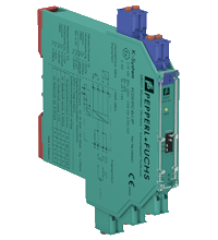
SMART Transmitter Power Supply KCD2-STC-Ex1.SP
- 1-channel isolated barrier
- 24 V DC supply (Power Rail)
- Input for 2-wire SMART transmitters and current sources
- Output for 4 mA ... 20 mA or 1 V ... 5 V
- Sink or source mode
- Housing width 12.5 mm
- Connection via spring terminals with push-in connection technology
- Up to SIL 2 acc. to IEC 61508


Please note: All product-related documents, such as certificates, declarations of conformity, etc., which were issued prior to the conversion under the name Pepperl+Fuchs GmbH or Pepperl+Fuchs AG, also apply to Pepperl+Fuchs SE.
Download the complete datasheet as a PDF:
Datasheet excerpt: Technical data of KCD2-STC-Ex1.SP
| Product Description |
|---|
| Input 4 mA ... 20 mA Output 4 mA ... 20 mA |
| General specifications | ||
|---|---|---|
| Signal type | Analog input | |
| Functional safety related parameters | ||
| Safety Integrity Level (SIL) | SIL 2 | |
| Supply | ||
| Connection | Power Rail or terminals 9+, 10- | |
| Rated voltage | 19 ... 30 V DC | |
| Ripple | ≤ 10 % | |
| Rated current | ≤ 45 mA | |
| Power dissipation | ≤ 800 mW | |
| Power consumption | ≤ 1.1 W | |
| Input | ||
| Connection side | field side | |
| Connection | terminals 1+, 2-; 3+, 4- | |
| Input signal | 4 ... 20 mA limited to approx. 30 mA | |
| Open circuit voltage/short-circuit current | terminals 1+, 2-: 22 V / 30 mA | |
| Voltage drop | terminals 3+, 4- : approx. 5 V | |
| Available voltage | terminals 1+, 2-: ≥ 15 V at 20 mA | |
| Output | ||
| Connection side | control side | |
| Connection | terminals 5-, 6+ | |
| Load | 0 ... 300 Ω (source mode) | |
| Output signal | 4 ... 20 mA or 1 ... 5 V (on 250 Ω, 0.1 % internal shunt) 4 ... 20 mA (sink mode), operating voltage 15.5 ... 26 V |
|
| Ripple | 20 mV rms | |
| Transfer characteristics | ||
| Deviation | at 20 °C (68 °F) ≤ ± 0.1 % incl. non-linearity and hysteresis (source mode 4 ... 20 mA) ≤ ± 0.2 % incl. non-linearity and hysteresis (sink mode 4 ... 20 mA) ≤ ± 0.2 % incl. non-linearity and hysteresis (source mode 1 ... 5 V) |
|
| Influence of ambient temperature | < 2 µA/K (0 ... 60 °C (32 ... 140 °F)); < 4 µA/K (-20 ... 0 °C (-4 ... 32 °F)) (source mode and sink mode 4 ... 20 mA) < 0.5 mV/K (0 ... 60 °C (32 ... 140 °F)); < 1 mV/K (-20 ... 0 °C (-4 ... 32 °F)) (source mode 1 ... 5 V) |
|
| Frequency range | field side into the control side: bandwidth with 0.5 Vpp signal 0 ... 3 kHz (-3 dB) control side into the field side: bandwidth with 0.5 Vpp signal 0 ... 3 kHz (-3 dB) |
|
| Settling time | ≤ 200 ms | |
| Rise time/fall time | ≤ 20 ms | |
| Galvanic isolation | ||
| Input/Output | reinforced insulation acc. to EN 50178, rated insulation voltage 300 Veff | |
| Input/power supply | reinforced insulation acc. to EN 50178, rated insulation voltage 300 Veff | |
| Output/power supply | reinforced insulation acc. to EN 50178, rated insulation voltage 300 Veff | |
| Indicators/settings | ||
| Display elements | LED | |
| Control elements | DIP switch | |
| Configuration | via DIP switches | |
| Labeling | space for labeling at the front | |
| Directive conformity | ||
| Electromagnetic compatibility | ||
| Directive 2014/30/EU | EN 61326-1:2013 (industrial locations) | |
| Conformity | ||
| Electromagnetic compatibility | NE 21:2006 | |
| Degree of protection | IEC 60529:2001 | |
| Ambient conditions | ||
| Ambient temperature | -20 ... 60 °C (-4 ... 140 °F) | |
| Mechanical specifications | ||
| Degree of protection | IP20 | |
| Connection | spring terminals | |
| Mass | approx. 100 g | |
| Dimensions | 12.5 x 114 x 124 mm (0.5 x 4.5 x 4.9 inch) , housing type A2 | |
| Height | 124 mm | |
| Width | 12.5 mm | |
| Length | 114 mm | |
| Mounting | on 35 mm DIN mounting rail acc. to EN 60715:2001 | |
| Data for application in connection with hazardous areas | ||
| EU-type examination certificate | CESI 06 ATEX 021 | |
| Marking |  II (1)G [Ex ia Ga] IIC , II (1)D [Ex ia Da] IIIC , I (M1) [Ex ia Ma] I II (1)G [Ex ia Ga] IIC , II (1)D [Ex ia Da] IIIC , I (M1) [Ex ia Ma] I |
|
| Input | [Ex ia Ga] IIC, [Ex ia Da] IIIC, [Ex ia Ma] I | |
| Supply | ||
| Maximum safe voltage | 250 V AC (Attention! Um is no rated voltage.) | |
| Equipment | terminals 1+, 2- | |
| Voltage | 25.2 V | |
| Current | 100 mA | |
| Power | 630 mW | |
| Internal capacitance | 5.7 nF | |
| Internal inductance | negligible | |
| Equipment | terminals 3+, 4- | |
| Voltage | < 30 V | |
| Current | < 128 mA | |
| Voltage | 7.2 V | |
| Current | 100 mA | |
| Power | 25 mW | |
| Internal capacitance | 5.7 nF | |
| Internal inductance | negligible | |
| Certificate | PF 06 CERT 0973 X | |
| Marking | II 3G Ex nA IIC T4 Gc |
|
| Galvanic isolation | ||
| Input/Output | safe electrical isolation acc. to IEC/EN 60079-11, voltage peak value 375 V | |
| Input/power supply | safe electrical isolation acc. to IEC/EN 60079-11, voltage peak value 375 V | |
| Directive conformity | ||
| Directive 2014/34/EU | EN 60079-0:2012+A11:2013 , EN 60079-11:2012 , EN 50303:2000 , EN 60079-15:2010 | |
| International approvals | ||
| FM approval | ||
| Control drawing | 116-0419 (cFMus) | |
| UL approval | ||
| Control drawing | 116-0420 (cULus) | |
| IECEx approval | IECEx CES 06.0001 | |
| Approved for | [Ex ia Ga] IIC , [Ex ia Da] IIIC , [Ex ia Ma] I | |
| General information | ||
| Supplementary information | Observe the certificates, declarations of conformity, instruction manuals, and manuals where applicable. For information see www.pepperl-fuchs.com. | |
| Accessories | ||
| Optional accessories | - power feed module KFD2-EB2(.R4A.B)(.SP) - universal power rail UPR-03(-M)(-S) - profile rail K-DUCT-BU(-UPR-03) |
|
Classifications
| System | Classcode |
|---|---|
| ECLASS 13.0 | 27210119 |
| ECLASS 12.0 | 27210119 |
| ECLASS 11.0 | 27210119 |
| ECLASS 10.0.1 | 27210119 |
| ECLASS 9.0 | 27210119 |
| ECLASS 8.0 | 27210119 |
| ECLASS 5.1 | 27210119 |
| ETIM 9.0 | EC001485 |
| ETIM 8.0 | EC001485 |
| ETIM 7.0 | EC001485 |
| ETIM 6.0 | EC001485 |
| ETIM 5.0 | EC001485 |
| UNSPSC 12.1 | 32101514 |
Details: KCD2-STC-Ex1.SP
Function
This isolated barrier is used for intrinsic safety applications.
The device supplies 2-wire SMART transmitters in a hazardous area, and can also be used with 2-wire SMART current sources.
It transfers the analog input signal to the safe area as an isolated current value.
Digital signals may be superimposed on the input signal in the hazardous or safe area and are transferred bi-directionally.
Selectable output of current source, sink mode, or voltage output is available via DIP switches.
If the HART communication resistance in the loop is too low, the internal resistance of 250 Ω between terminals 6 and 8 can be used.
Test sockets for the connection of HART communicators are integrated into the terminals of the device.
Product Documentation: KCD2-STC-Ex1.SP
| Safety and Security Documentation | Language | File Type | File Size |
|---|---|---|---|
| Instruction manual | ENG | 50 KB | |
| Manual | ENG | 531 KB | |
| Manuals | |||
| Manual | ENG | 3685 KB | |
Design / Simulation: KCD2-STC-Ex1.SP
| CAD | Language | File Type | File Size |
|---|---|---|---|
| CAD 2-D / CAD 2-D | ALL | ZIP | 458 KB |
| CAD 3-D / CAD 3-D | ALL | STP | 179 KB |
| CAD Portal / CAD Portal | ALL | LINK | --- |
Approvals: KCD2-STC-Ex1.SP
| Certificates | Certificate No. | Language | File Type | File Size |
|---|---|---|---|---|
| Brasil TUV Rheinland Brazil | TÜV 13.1149 X (Singapore) | ALL | 444 KB | |
| Canada FM | FM18CA0116X | ALL | 2690 KB | |
| Canada UL cUL | E106378 cUL (QUZW7) | ALL | LINK | --- |
| Europe CESI II (1) D II (1) G I (M1) ATEX | CESI 06 ATEX 021 X | ALL | 622 KB | |
| USA Canada UL Hazardous Location Certificate of Compliance cULus UL E106378 | CoC 20170501 - E106378 RepRef 20081022 | ALL | 244 KB | |
| USA FM | FM19US0117X | ALL | 2447 KB | |
| USA UL | E106378 UL (QUZW) | ALL | LINK | --- |
| Control Drawings | ||||
| Control drawing UL / Control drawing UL | ALL | 209 KB | ||
| Control drawing FM / Control drawing FM | ALL | 208 KB | ||
Associated Products: KCD2-STC-Ex1.SP
| Accessories | ||||||
|---|---|---|---|---|---|---|
|
||||||
|
||||||
|
||||||
|
||||||
|
||||||
|
||||||
|
||||||
|
||||||
|
||||||


Choose from various selection criteria like safety integrity level, performance level, device function, and signal type and find the SIL/PL assessed device that you are looking for.


Pepperl+Fuchs SE
Lilienthalstraße 200
68307 Mannheim
Germany
info@de.pepperl-fuchs.com
 +49 621 776-0
Pepperl+Fuchs is a leading developer and manufacturer of electronic sensors and components for the global automation market. Continuous innovation, enduring quality, and steady growth have been the foundation of our success for more than 70 years. Pepperl+Fuchs employs 6,300 people worldwide and has manufacturing facilities in Germany, USA, Singapore, Hungary, Indonesia and Vietnam, most of them ISO 9001 certified.