

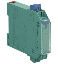
SMART Transmitter Power Supply KFD2-STC3-Ex1
- 1-channel isolated barrier
- 24 V DC supply (Power Rail)
- 2-wire SMART transmitter
- Output 4 mA ... 20 mA
- SMART capable up to 40 kHz (-1dB)
- Suitable for Honeywell DE protocol
- Terminals with test points


Please note: All product-related documents, such as certificates, declarations of conformity, etc., which were issued prior to the conversion under the name Pepperl+Fuchs GmbH or Pepperl+Fuchs AG, also apply to Pepperl+Fuchs SE.
Download the complete datasheet as a PDF:
Datasheet excerpt: Technical data of KFD2-STC3-Ex1
| Product Description |
|---|
| Output 4 ... 20 mA |
| General specifications | ||
|---|---|---|
| Signal type | Analog input | |
| Supply | ||
| Connection | Power Rail or terminals 7+, 8- | |
| Rated voltage | 20 ... 35 V DC | |
| Ripple | within the supply tolerance | |
| Power dissipation | ≤ 1.6 W | |
| Power consumption | ≤ 2 W | |
| Interface | ||
| Protocol | Honeywell DE | |
| Input | ||
| Connection side | field side | |
| Connection | terminals 1+, 3- | |
| Input signal | 4 ... 20 mA | |
| Available voltage | approx. 17 V at 4 ... 20 mA | |
| Output | ||
| Connection side | control side | |
| Connection | terminals 9+, 10-, 11+ | |
| Output signal | 4 ... 20 mA , max. load 1000 Ω , for HART ≥ 230 Ω, Honeywell DE 230 ... 280 Ω (transmitter and communicator dependent) | |
| Ripple | ≤ 0.05 % of output signal range | |
| Transfer characteristics | ||
| Deviation | ≤ 0.05 % of output signal range (current output), ≤ 10 µA at 20 °C (68 °F) | |
| Influence of ambient temperature | ≤ 20 ppm/K | |
| Frequency range | field side into the control side: bandwidth with 1 mApp signal 0 ... 40 kHz (-1 dB); 0 ... 50 kHz (-6 dB) safe area to hazardous area: bandwidth with 250 mVpp signal 2 Hz ... 40 kHz (-1 dB); 1 Hz ... 50 kHz (-6 dB) |
|
| Rise time | 10 µs | |
| Galvanic isolation | ||
| Output/power supply | functional insulation, rated insulation voltage 50 V AC | |
| Indicators/settings | ||
| Display elements | LED | |
| Labeling | space for labeling at the front | |
| Directive conformity | ||
| Electromagnetic compatibility | ||
| Directive 2014/30/EU | EN 61326-1:2013 (industrial locations) | |
| Conformity | ||
| Electromagnetic compatibility | NE 21:2006 | |
| Degree of protection | IEC 60529:2001 | |
| Ambient conditions | ||
| Ambient temperature | -20 ... 60 °C (-4 ... 140 °F) | |
| Mechanical specifications | ||
| Degree of protection | IP20 | |
| Connection | screw terminals | |
| Mass | approx. 150 g | |
| Dimensions | 20 x 115 x 115 mm (0.8 x 4.5 x 4.5 inch) , housing type B1 | |
| Height | 115 mm | |
| Width | 20 mm | |
| Length | 115 mm | |
| Mounting | on 35 mm DIN mounting rail acc. to EN 60715:2001 | |
| Data for application in connection with hazardous areas | ||
| EU-type examination certificate | BAS 01 ATEX 7369 | |
| Marking |  II (1)G [Ex ia Ga] IIC , II (1)D [Ex ia Da] IIIC , I (M1) [Ex ia Ma] I II (1)G [Ex ia Ga] IIC , II (1)D [Ex ia Da] IIIC , I (M1) [Ex ia Ma] I |
|
| Input | [Ex ia Ga] IIC, [Ex ia Da] IIIC, [Ex ia Ma] I | |
| Voltage | 25.2 V DC | |
| Current | 93 mA | |
| Power | 587 mW | |
| Supply | ||
| Maximum safe voltage | 250 V (Attention! The rated voltage can be lower.) | |
| Certificate | BASEEFA 09 ATEX 0218X | |
| Marking | II 3G Ex nA II T4 Gc [device in zone 2] |
|
| Galvanic isolation | ||
| Input/Output | safe electrical isolation acc. to IEC/EN 60079-11, voltage peak value 375 V | |
| Input/power supply | safe electrical isolation acc. to IEC/EN 60079-11, voltage peak value 375 V | |
| Directive conformity | ||
| Directive 2014/34/EU | EN 60079-0:2012+A11:2013 , EN 60079-11:2012 , EN 60079-15:2010 | |
| International approvals | ||
| UL approval | ||
| Control drawing | 116-0173 (cULus) | |
| IECEx approval | ||
| IECEx certificate | IECEx BAS 06.0088 IECEx BAS 09.0102X |
|
| IECEx marking | [Ex ia Ga] IIC , [Ex ia Da] IIIC , [Ex ia Ma] I Ex nA IIC T4 Gc |
|
| General information | ||
| Supplementary information | Observe the certificates, declarations of conformity, instruction manuals, and manuals where applicable. For information see www.pepperl-fuchs.com. | |
| Accessories | ||
| Optional accessories | - power feed module KFD2-EB2(.R4A.B)(.SP) - universal power rail UPR-03(-M)(-S) - profile rail K-DUCT-BU(-UPR-03) |
|
Classifications
| System | Classcode |
|---|---|
| ECLASS 13.0 | 27210119 |
| ECLASS 12.0 | 27210119 |
| ECLASS 11.0 | 27210119 |
| ECLASS 10.0.1 | 27210119 |
| ECLASS 9.0 | 27210119 |
| ECLASS 8.0 | 27210119 |
| ECLASS 5.1 | 27210119 |
| ETIM 9.0 | EC001485 |
| ETIM 8.0 | EC001485 |
| ETIM 7.0 | EC001485 |
| ETIM 6.0 | EC001485 |
| ETIM 5.0 | EC001485 |
| UNSPSC 12.1 | 32101514 |
Details: KFD2-STC3-Ex1
Function
This isolated barrier is used for intrinsic safety applications. It provides a 2-wire SMART transmitter with power in a hazardous area and transfers the analog signal to the safe area as an isolated current source.
Digital signals up to 40 kHz may be superimposed on the analog values in the hazardous or safe area and are transferred bi-directionally.
Sockets for the connection of a HART communicator are integrated into the terminals of the device.
Product Documentation: KFD2-STC3-Ex1
| Safety and Security Documentation | Language | File Type | File Size |
|---|---|---|---|
| Instruction manual | ENG | 50 KB | |
| Manuals | |||
| Manual | ENG | 3685 KB | |
Design / Simulation: KFD2-STC3-Ex1
| CAD | Language | File Type | File Size |
|---|---|---|---|
| CAD 2-D / CAD 2-D | ALL | ZIP | 450 KB |
| CAD 3-D / CAD 3-D | ALL | STP | 105 KB |
Approvals: KFD2-STC3-Ex1
| Certificates | Certificate No. | Language | File Type | File Size |
|---|---|---|---|---|
| Baseefa IECEx Certificate of Conformity | IECEx BAS 06.0088 | ALL | LINK | --- |
| Baseefa IECEx Certificate of Conformity | IECEx BAS 09.0102X | ALL | LINK | --- |
| Canada UL cUL | E106378 cUL (QUZW7) | ALL | LINK | --- |
| Europe Baseefa ATEX Category 3 G | Baseefa 09 ATEX 0218X | ALL | 1952 KB | |
| Europe Baseefa Group I (M1) ATEX Category (1) GD | BAS 01 ATEX 7369 | ALL | 2968 KB | |
| India PESO (India) CCOE | A/P/HQ/KA/104/5865 (P506128) | ALL | 101 KB | |
| USA Canada UL Hazardous Location Certificate of Compliance cULus UL E106378 | CoC 20140902 - E106378 RepRef 20011030 | ALL | 429 KB | |
| USA UL | E106378 UL (QUZW) | ALL | LINK | --- |
| Control Drawings | ||||
| Control drawing UL / Control drawing UL | ALL | 1092 KB | ||
| Declaration of Conformity | ||||
| EU Declaration of Conformity (P+F) / EU-Konformitäterklärung (P+F) | DOC-0365G | ALL | 82 KB | |
Associated Products: KFD2-STC3-Ex1
| Accessories | ||||||
|---|---|---|---|---|---|---|
|
||||||
|
||||||
|
||||||
|
||||||
|
||||||
|
||||||
|
||||||
|
||||||
|
||||||


Choose from various selection criteria like safety integrity level, performance level, device function, and signal type and find the SIL/PL assessed device that you are looking for.


Pepperl+Fuchs SE
Lilienthalstraße 200
68307 Mannheim
Germany
info@de.pepperl-fuchs.com
 +49 621 776-0
Pepperl+Fuchs is a leading developer and manufacturer of electronic sensors and components for the global automation market. Continuous innovation, enduring quality, and steady growth have been the foundation of our success for more than 70 years. Pepperl+Fuchs employs 6,300 people worldwide and has manufacturing facilities in Germany, USA, Singapore, Hungary, Indonesia and Vietnam, most of them ISO 9001 certified.