

2-Wire Sensors
2-Wire Sensors for Direct-Current Voltage Operation
2-wire sensors are operated in series to the connected load. There are no separate connections for the load circuit and the voltage supply of a 2-wire sensor.
2-Wire Sensor: Never Fully Conductive—Never Fully Locked
A 2-wire sensor is an active component that requires energy to function. The sensor is supplied with this electrical energy via the two connecting wires. At the same time, the sensor signals its switch state via the same two connecting wires. Theoretically, the sensor is easily replaced by a mechanical switch that is open or closed depending on the sensor damping situation.
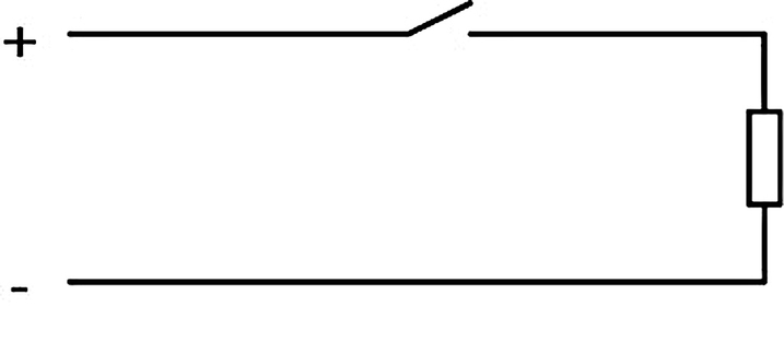
Switch open
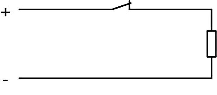
Switch closed
This conceptual simplification does not adequately reflect reality. No current flows through an ideal open switch. The connected load is not energized. Conversely, voltage does not drop through a closed switch in an ideal situation. The entire supply voltage is applied across the load.
Unlike a mechanical switch, a two-wire sensor as an active component requires voltage and current at all times. This means that even when closed, a non-negligible voltage, missing from the connected load, drops across the sensor. When open, a current flows through the sensor and the connected load. Therefore, there will never be clear cases of "open" and "closed"—as is the case with mechanical switching contacts—when operating a two-wire sensor.
"Open" Operating State
In the "open" operating state, the switching element is nonconductive. Current still flows in the circuit, because the sensor electronics have a specific current requirement. This is usually is quite low, generally values of less than 1 mA. Nevertheless, this low current value can generate a voltage on high-impedance loads, such as the digital input of a control panel with a typical input impedance of several kilohms. This voltage can simulate a high level at the digital input.
Modern digital inputs (type 3 according to EN 61131-2) are designed to have high impedance to reduce input currents and therefore cut power dissipation and waste heat. To meet the input characteristic values of such modern digital inputs, Pepperl+Fuchs offers two-wire sensors that have a particularly low residual current.
Example: NBB10-30GS50-Z4L-V1. The "L" in the output name stands for low current.
"Closed" Operating State
In the "closed" operating state, the switching element is conductive. Current is flowing in the circuit. Unlike with a mechanical contact, a voltage drops across the sensor in the range of several volts.
When operating the sensor at low supply voltages, the voltage drop across the connected sensor can cause too little voltage to reach the load. In this case, the digital input of a control panel does not receive enough voltage to detect that the sensor is switching.
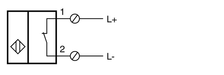
Sensor Connection—Example
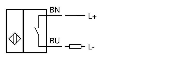
Example of 2-wire sensor in direct-current voltage operation
The order of the sensor and the load is not important in a series connection.
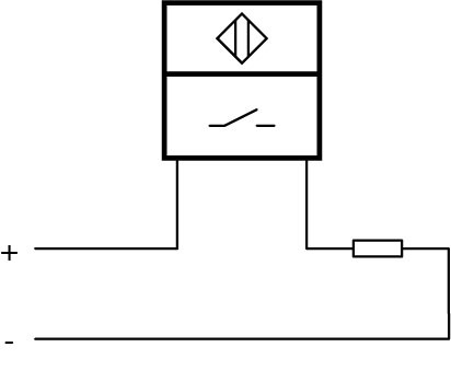 | corresponds to | 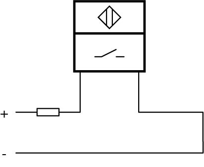 |
The two sensor and load arrangements shown are entirely equivalent and interchangeable.
Reverse Polarity Protection
2-wire sensors for direct-current voltage operation from Pepperl+Fuchs are protected against damage by reverse polarity. Reverse polarity protection is implemented in different ways and is identified in the product's technical data.
We distinguish the following types of reverse polarity protection.
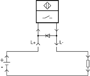
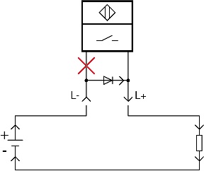
Reverse polarity protected
Reverse polarity protected sensors are protected by an internal diode against damage caused by reverse polarity. The sensor will not work if the polarity is incorrect. No current flows in the circuit. A digital control input receives a continuous low signal.
| Sensor is working—current flows as intended | Sensor is not working—current flows | |
|---|---|---|
 |
 |
Voltage polarity independent
Voltage polarity independent sensors are always correctly supplied by an internal circuit trick and always function correctly regardless of the external polarity.
The internal circuit, which ensures that the internal polarity of the sensor electronics is always correct, causes a slightly higher voltage drop compared to reverse polarity protected or reverse conducting sensors.
2-Wire Sensor Versions
The electrical output version is usually specified in the third block of the Pepperl+Fuchs order designation. A 2-wire sensor is marked with a "Z."
| Abbreviation | Meaning | Special feature |
|---|---|---|
| Z or Z0 | Normally-open, voltage polarity independent | Voltage drop ≤ 5 V |
| Z1 | Normally-closed, voltage polarity independent | Voltage drop ≤ 5 V |
| Z2 | Normally-closed/normally-open, wiring-programmed, voltage polarity independent | Voltage drop ≤ 5 V |
| Z3 | Normally-open, voltage polarity independent | Like Z0, but different plug pinout |
| Z4 | Normally-open, reverse polarity protected | Voltage drop ≤ 3.8 V |
| Z4L | Normally-open, reverse polarity protected | Like Z4, but less residual current |
| Z5 | Normally-closed, reverse polarity protected | Voltage drop ≤ 3.8 V |
| Z7 | Normally-closed, reverse polarity protected | Like Z5, but different plug pin assignment |
| Z8 | 2 normally-open, voltage polarity independent |
2-Wire Sensors for Alternating-Current Voltage Operation
2-wire sensors of this type are operated in series with the load and are connected to alternating-current supply voltages. Otherwise, the same statements apply as for two-wire sensors for direct-current voltage operation.
Sensor Connection—Example
Example of 2-wire sensor in alternating-current voltage operation
Versions
Sensors of this type are marked with a –W in the third block of the order designation.
Such sensors are available in the following switching element functions:
- Normally-closed (WO)
- Normally-open (WS)
- Normally-closed or normally-open (W), wiring-programmable
2-Wire Sensors for Direct-Current Voltage or Alternating-Current Voltage Operation
2-wire sensors of this type are operated in series with the load and can be connected to either direct-current or alternating-current supply voltages. Otherwise, the same statements apply as for two-wire sensors for direct-current voltage operation.
Sensor Connection—Example
Example of 2-wire sensor in direct-current voltage or alternating-current voltage operation
Versions
Sensors of this type are marked with a –U in the third block of the Pepperl+Fuchs order designation.
These sensors are available in the following switching element functions:
- Normally-closed (UO)
- Normally-open (US)
- Normally-closed or normally-open (UU), wiring-programmable
2-Wire Sensors According to NAMUR
2-wire sensors according to NAMUR (NAMUR sensors) are named after the User Association of Automation Technology in Process Industries (original German name: "Normenarbeitsgemeinschaft für Mess- und Regeltechnik der chemischen Industrie", in short: NAMUR). These are two-wire sensors according to EN 60947-5-6 (VDE 0660, part 212) that have a continuous or a noncontinuous distance/current characteristic.
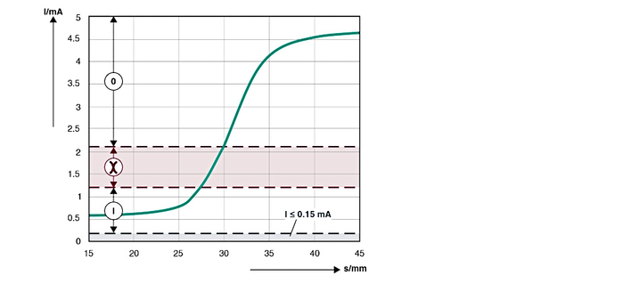
Area 0: unactuated area
Red area between 0/I: impermissible area of the switch amplifier
Area I: actuated range
Area ≤ 0.15 mA: lead breakage
Area ≥ 6.5 mA: short circuit
In addition, Pepperl+Fuchs offers NAMUR sensors with binary switching characteristics. NAMUR sensors with this output characteristic are marked with "N0" (normally-closed characteristics) or "N1" (normally-open characteristics) in the type designation.
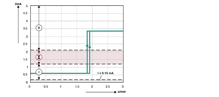
Area 0: unactuated area
Red area between 0/I: impermissible area of the switch amplifier
Area I: actuated range
Area ≤ 0.15 mA: lead breakage
Area ≥ 6.5 mA: short circuit
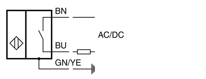
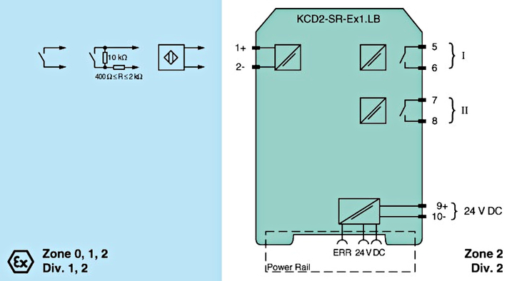
Sensor Connection—Example
Example of a 2-wire sensor according to NAMUR
Pepperl+Fuchs offers various switch amplifiers for NAMUR sensors for explosion-protection applications and standard applications.
Note: In explosion-protection applications, the operating location of the intrinsically safe NAMUR sensor is located in the explosion-hazardous area. The isolated switch amplifier must be installed outside the explosion-hazardous area.
A blue-sheathed sensor cable visually identifies the NAMUR circuit as intrinsically safe.
Example:
NAMUR Sensor Versions
NAMUR sensors are marked with the following in the third block of the Pepperl+Fuchs order designation:
–N = continuous distance/current characteristic or
–N0 = non-continuous distance/current characteristic
The sensors are available in the following switching functions:
- Normally-closed (N/N0)
- Normally-open (1N/N1)
- Normally-closed 2-channel (N4)
NAMUR sensors are usually connected to external switch amplifiers that convert the current variation into a binary output signal.
2-Wire Safety Sensors According to NAMUR
This type of 2-wire safety sensor corresponds to NAMUR sensors with special safety logic. These sensors are marked accordingly with SN or S1N.
In combined operation with approved control units, these sensors establish a safe state if a fault occurs.
Example: If the cordset between the sensor and the control unit malfunctions or fails, the control unit output automatically switches to the "OFF" safe state.
Note: In safety-related applications, the sensor must be operated on an approved safety switch amplifier from Pepperl+Fuchs (e.g., KFD2-SH-EX1).
Observe the "exida Functional Safety Assessment" document, which belongs to this sensor and is available as part of the product documentation from www.pepperl-fuchs.com.
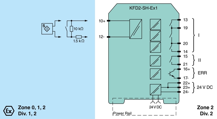
Sensor Connection—Example
The following diagram is a sample circuit of a safety sensor with the KFD2-SH-EX1. The implemented safety logic should be considered functionally independent of the galvanic isolation for establishing intrinsic safety.
The two components in this circuit enable the safe state to be established in a failure. Additionally, and independently of this function, the circuit is intrinsically safe.
Versions of 2-Wire Safety Sensors According to NAMUR
Sensors of this type are marked with the following in the third block of the Pepperl+Fuchs order designation:
–SN (switching element function "normally-closed") or
–S1N (switching element function "normally-open")
Safety sensors of this type are designed for use with safety isolated switch amplifiers of type SH from Pepperl+Fuchs up to SIL 3 according to IEC 61508.


Pepperl+Fuchs AB
Bultgatan 40 A
442 40 Kungälv
Sverige
orgnr. 556212-2126
info@se.pepperl-fuchs.com
 +46 303 246070
Pepperl+Fuchs is a leading developer and manufacturer of electronic sensors and components for the global automation market. Continuous innovation, enduring quality, and steady growth have been the foundation of our success for more than 70 years. Pepperl+Fuchs employs 6,300 people worldwide and has manufacturing facilities in Germany, USA, Singapore, Hungary, Indonesia and Vietnam, most of them ISO 9001 certified.