

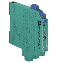
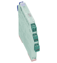
Universal Temperature Converter KCD2-UT2-Ex1
- 1-channel isolated barrier
- 24 V DC supply (Power Rail)
- Thermocouple, RTD, potentiometer or voltage input
- Current output 0/4 mA ... 20 mA
- Sink or source mode
- Configurable by PACTware
- Line fault (LFD) and sensor burnout detection
- Up to SIL 2 acc. to IEC/EN 61508 / IEC/EN 61511


 Contact Us
Please note: All product-related documents, such as certificates, declarations of conformity, etc., which were issued prior to the conversion under the name Pepperl+Fuchs GmbH or Pepperl+Fuchs AG, also apply to Pepperl+Fuchs SE.
Download the complete datasheet as a PDF:
Datasheet excerpt: Technical data of KCD2-UT2-Ex1
| General specifications | ||
|---|---|---|
| Signal type | Analog input | |
| Functional safety related parameters | ||
| Safety Integrity Level (SIL) | SIL 2 | |
| Supply | ||
| Connection | terminals 9+, 10- or power feed module/Power Rail | |
| Rated voltage | 19 ... 30 V DC | |
| Ripple | within the supply tolerance | |
| Power dissipation | ≤ 0.98 W | |
| Power consumption | max. 0.98 W | |
| Interface | ||
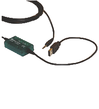
| Programming interface | programming socket | |
| Input | ||
| Connection side | field side | |
| Connection | terminals 1, 2, 3, 4 | |
| RTD | type Pt10, Pt50, Pt100, Pt500, Pt1000 (EN 60751: 1995) type Pt10GOST, Pt50GOST, Pt100GOST, Pt500GOST, Pt1000GOST (6651-94) type Cu10, Cu50, Cu100 (P50353-92) type Ni100 (DIN 43760) |
|
| Measuring current | approx. 200 µA with RTD | |
| Types of measuring | 2-, 3-, 4-wire connection | |
| Lead resistance | max. 50 Ω per line | |
| Measurement loop monitoring | sensor breakage, sensor short-circuit | |
| Thermocouples | type B, E, J, K, N, R, S, T (IEC 584-1: 1995) type L (DIN 43710: 1985) type TXK, TXKH, TXA (P8.585-2001) |
|
| Cold junction compensation | external and internal | |
| Measurement loop monitoring | sensor breakage | |
| Potentiometer | 0 ... 20 kΩ (2-wire connection), 0.8 ... 20 kΩ (3-wire connection) | |
| Voltage | selectable within the range -100 ... 100 mV | |
| Input resistance | ≥ 1 MΩ (-100 ... 100 mV) | |
| Output | ||
| Connection side | control side | |
| Connection | terminal 5: source (-), terminal 6: source (+), terminal 7: sink(-), terminal 8: sink (+) | |
| Output | Analog current output | |
| Current range | 0 ... 20 mA or 4 ... 20 mA | |
| Fault signal | downscale 0 or 2 mA, upscale 21.5 mA (acc. NAMUR NE43) | |
| Source | load 0 ... 550 Ω open-circuit voltage ≤ 18 V |
|
| Sink | Voltage across terminals 5 ... 30 V. If the current is supplied from a source > 16.5 V, series resistance of ≥ (V - 16.5)/0.0215 Ω is needed, where V is the source voltage. The maximum value of the resistance is (V - 5)/0.0215 Ω. |
|
| Transfer characteristics | ||
| Deviation | ||
| After calibration | Pt100: ± (0.06 % of measurement value in K + 0.1 % of span + 0.1 K (4-wire connection)) thermocouple: ± (0.05 % of measurement value in °C + 0.1 % of span + 1.5 K (1.7 K for types R and S)) , includes ± 1.3 K fault of the cold junction compensation (CJC) mV: ± (50 µV + 0.1 % of span) potentiometer: ± (0.05 % of full scale + 0.1 % of span, (excludes faults due to lead resistance)) |
|
| Influence of ambient temperature | Pt100: ± (0.0015 % of measurement value in K + 0.006 % of span)/K ΔTamb*) thermocouple: ± (0.02 K + 0.005 % of measurement value in °C + 0.006 % of span)/K ΔTamb*)), influence of cold junction compensation (CJC) included mV: ± (0.01 % of measurement value + 0.006 % of span)/K ΔTamb*) potentiometer: ± 0.006 % of span/K ΔTamb*) *) ΔTamb = ambient temperature change referenced to 23 °C (296 K) |
|
| Influence of supply voltage | < 0.01 % of span | |
| Influence of load | ≤ 0.001 % of output value per 100 Ω | |
| Reaction time | worst case value (sensor breakage and/or sensor short circuit detection enabled) mV: 1 s, thermocouples with CJC: 1.1 s, thermocouples with fixed reference temperature: 1.1 s, 3- or 4-wire RTD: 920 ms, 2-wire RTD: 800 ms, Potentiometer: 2.05 s |
|
| Galvanic isolation | ||
| Output/supply, programming input | functional insulation, rated insulation voltage 50 V AC There is no electrical isolation between the programming input and the supply. The programming cable provides galvanic isolation so that ground loops are avoided. |
|
| Indicators/settings | ||
| Display elements | LEDs | |
| Configuration | via PACTware | |
| Labeling | space for labeling at the front | |
| Directive conformity | ||
| Electromagnetic compatibility | ||
| Directive 2014/30/EU | EN 61326-1:2013 (industrial locations) | |
| Conformity | ||
| Electromagnetic compatibility | NE 21:2012 EN 61326-3-2:2008 |
|
| Degree of protection | IEC 60529:2001 | |
| Protection against electrical shock | UL 61010-1:2004 | |
| Ambient conditions | ||
| Ambient temperature | -20 ... 70 °C (-4 ... 158 °F) | |
| Mechanical specifications | ||
| Degree of protection | IP20 | |
| Connection | screw terminals | |
| Mass | approx. 100 g | |
| Dimensions | 12.5 x 119 x 114 mm (0.5 x 4.7 x 4.5 inch) (W x H x D) , housing type A2 | |
| Height | 119 mm | |
| Width | 12.5 mm | |
| Depth | 114 mm | |
| Mounting | on 35 mm DIN mounting rail acc. to EN 60715:2001 | |
| Data for application in connection with hazardous areas | ||
| EU-type examination certificate | BASEEFA 13 ATEX 0102 X | |
| Marking |  II (1)G [Ex ia Ga] IIC , II (1)D [Ex ia Da] IIIC , I (M1) [Ex ia Ma] I II (1)G [Ex ia Ga] IIC , II (1)D [Ex ia Da] IIIC , I (M1) [Ex ia Ma] I |
|
| Input | [Ex ia Ga] IIC, [Ex ia Da] IIIC, [Ex ia Ma] I | |
| Inputs | terminals 1, 2, 3, 4 | |
| Voltage | 9 V | |
| Current | 13.1 mA | |
| Power | 30 mW | |
| Analog outputs, power supply, collective error | ||
| Maximum safe voltage | 250 V (Attention! This is not the rated voltage.) | |
| Interface | ||
| Maximum safe voltage | 250 V (Attention! The rated voltage is lower.), RS 232 | |
| Certificate | BASEEFA 13 ATEX 0103 X | |
| Marking | II 3G Ex nA IIC T4 Gc |
|
| Galvanic isolation | ||
| Input/Other circuits | safe electrical isolation acc. to IEC/EN 60079-11, voltage peak value 375 V | |
| Directive conformity | ||
| Directive 2014/34/EU | EN IEC 60079-0:2018+AC:2020 , EN 60079-11:2012 , EN 60079-15:2010 | |
| International approvals | ||
| UL approval | ||
| Control drawing | 116-0379 (cULus) | |
| IECEx approval | ||
| IECEx certificate | IECEx BAS 13.0057X | |
| IECEx marking | [Ex ia Ga] IIC, [Ex ia Da] IIIC, [Ex ia Ma] I | |
| General information | ||
| Supplementary information | Observe the certificates, declarations of conformity, instruction manuals, and manuals where applicable. For information see www.pepperl-fuchs.com. | |
Classifications
| System | Classcode |
|---|---|
| ECLASS 13.0 | 27210129 |
| ECLASS 12.0 | 27210129 |
| ECLASS 11.0 | 27210129 |
| ECLASS 10.0.1 | 27210129 |
| ECLASS 9.0 | 27210129 |
| ECLASS 8.0 | 27210190 |
| ECLASS 5.1 | 27210107 |
| ETIM 9.0 | EC002919 |
| ETIM 8.0 | EC002919 |
| ETIM 7.0 | EC002919 |
| ETIM 6.0 | EC002919 |
| ETIM 5.0 | EC001485 |
| UNSPSC 12.1 | 32101514 |
Details: KCD2-UT2-Ex1
Function
This isolated barrier is used for intrinsic safety applications.
The device converts RTD input signals or thermocouple input signals in the hazardous area to 0/4 mA ... 20mA signals in the safe area.
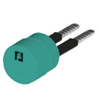
The removable terminal block KC-CJC-** is available for thermocouples when internal cold junction compensation is desired.
A fault is indicated by an LED and by user-configured fault indication outputs.
If the device is operated via Power Rail, additionally a collective error message is available.
The device is easily configured by the use of the PACTware configuration software.
For additional information, refer to the manual and www.pepperl-fuchs.com.
Informative Literature: KCD2-UT2-Ex1
| Literature | Language | File Type | File Size |
|---|---|---|---|
| Application Report - Energy Generation in Wastwater Treatment Plants | ENG | 532 KB | |
| Application Report - Generating Electricity in Coal-Fired Power Plants | ENG | 412 KB | |
| Application Report - Screening Systems in Sewage Treatment Plants | ENG | 577 KB | |
| Application Report - Sicherer Brennstofftransport in Kohlekraftwerken | ENG | 391 KB | |
| Application Report - Water Inlet in Wastewater Treatment Plants | ENG | 526 KB |
Product Documentation: KCD2-UT2-Ex1
| Safety and Security Documentation | Language | File Type | File Size |
|---|---|---|---|
| Instruction manual | ENG | 170 KB | |
| Functional Safety Manual | ENG | 1542 KB | |
| Manuals | |||
| Manual KCD2-UT2-(Ex)1 | ENG | 1060 KB | |
| Manual | ENG | 3685 KB | |
| Installation and configuration guide Device Type Manager (DTM) | ENG | 8665 KB | |
Design / Simulation: KCD2-UT2-Ex1
| CAD | Language | File Type | File Size |
|---|---|---|---|
| CAD 3-D / CAD 3-D | ALL | STP | 3085 KB |
| CAD Portal / CAD Portal | ALL | LINK | --- |
| CAE | |||
| CAE EPLAN Data Portal / CAE EPLAN Data Portal | ALL | LINK | --- |
| CAE EPLAN macro EDZ / CAE EPLAN Makro EDZ | ALL | EDZ | 1690 KB |
Approvals: KCD2-UT2-Ex1
| Certificates | Certificate No. | Language | File Type | File Size |
|---|---|---|---|---|
| China SITIIAS CCC Ex Certificate | 2020322316001219 (Singapore) | ALL | 1047 KB | |
| DNV Marine | TAA00001WX | ALL | 106 KB | |
| Europe Baseefa II (1) G Group I (M1) II (1) D ATEX Category (1) GD | Baseefa 13 ATEX 0102X | ALL | 557 KB | |
| Europe Baseefa II 3 G ATEX Category 3 G | Baseefa 13 ATEX 0103X | ALL | 457 KB | |
| IECEx Certificate of Conformity | IECEx BAS 13.0057X | ALL | LINK | --- |
| Korea KOSHA | 21-AV4BO-0066X | ALL | 722 KB | |
| Korea KOSHA | 21-AV4BO-0065X | ALL | 728 KB | |
| South Africa MASC | MASC MS/18-2258X | ALL | 745 KB | |
| USA Canada UL Hazardous Location Certificate of Compliance cULus UL E106378 | CoC E106378 RepRef E106378-20130720 | ALL | 355 KB | |
| Control Drawings | ||||
| Control drawing UL / Control drawing UL | ALL | 46 KB | ||
| Declaration of Conformity | ||||
| EU Declaration of Conformity (P+F) / EU-Konformitäterklärung (P+F) | DOC-0164F | ALL | 194 KB | |
Software: KCD2-UT2-Ex1
| Frameworks | Release Info | File Type | File Size |
|---|---|---|---|
| PACTware 4.1 SP6 / PACTware 4.1 SP6 | 4.1.0.53 | ZIP | 43327 KB |
| PACTware 5.0 / PACTware 5.0 | 5.0.5.31 | ZIP | 44203 KB |
| Device Description Files/Drivers | |||
| DTM Collection Interface Technology 2 / DTM Collection Interface Technology 2 | 1.4.110.76 | ZIP | 32633 KB |
Associated Products: KCD2-UT2-Ex1
| Matching System Components | ||||||
|---|---|---|---|---|---|---|
|
||||||
|
||||||
|
||||||
|
||||||
|
||||||
|
||||||
|
||||||
|
||||||
|
||||||
| Accessories | ||||||
|
||||||
|
||||||
|
||||||
|
||||||
|
||||||
|
||||||


- Ask an Expert
- Cross Reference Request
- Check order status
- News
- NetPartner Login
- Subscribe to Gate-Way, our Process Automation Division e-newsletter
- Service Level Agreements for ecom instruments
- Find a Local Distributor or Representative
- Literature
- Technologies
- Control System Solutions
- Download Technical Documents
- Press Releases
- International Trade Shows

Choose from various selection criteria like safety integrity level, performance level, device function, and signal type and find the SIL/PL assessed device that you are looking for.


Pepperl+Fuchs Inc.
1600 Enterprise Parkway
Twinsburg, OH 44087
United States of America
sales@us.pepperl-fuchs.com
 +1 330 425-3555
Pepperl+Fuchs is a leading developer and manufacturer of electronic sensors and components for the global automation market. Continuous innovation, enduring quality, and steady growth have been the foundation of our success for more than 70 years. Pepperl+Fuchs employs 6,300 people worldwide and has manufacturing facilities in Germany, USA, Singapore, Hungary, Indonesia and Vietnam, most of them ISO 9001 certified. Pepperl+Fuchs does not sell personal data.