

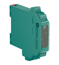
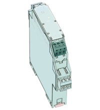
SMART Transmitter Power Supply KFD2-STC5-2
- 2-channel signal conditioner
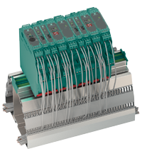
- 24 V DC supply (Power Rail)
- Input 2-wire and 3-wire SMART transmitters and 2-wire SMART current sources
- Output 4 mA ... 20 mA current sink/current source
- Terminals with test points
- Up to SIL 2 acc. to IEC/EN 61508


 Contact Us
Please note: All product-related documents, such as certificates, declarations of conformity, etc., which were issued prior to the conversion under the name Pepperl+Fuchs GmbH or Pepperl+Fuchs AG, also apply to Pepperl+Fuchs SE.
Download the complete datasheet as a PDF:
Datasheet excerpt: Technical data of KFD2-STC5-2
| General specifications | ||
|---|---|---|
| Signal type | Analog input | |
| Functional safety related parameters | ||
| Safety Integrity Level (SIL) | SIL 2 | |
| Supply | ||
| Connection | Power Rail or terminals 14+, 15- | |
| Rated voltage | 18 ... 30 V DC | |
| Ripple | within the supply tolerance | |
| Power dissipation | ≤ 1.4 W at maximum load | |
| Power consumption | ≤ 2.6 W at maximum load | |
| Input | ||
| Connection side | field side | |
| Connection | terminals 1+, 2-, 3; 4+, 5-, 6 | |
| Input signal | 4 ... 20 mA | |
| Open circuit voltage/short-circuit current | terminals 1+, 3; 4+, 6: 23 V / 25 mA | |
| Input resistance | max. 265 Ω terminals 2-, 3; 5-, 6 , max. 330 Ω terminals 1+, 3; 4+, 6 | |
| Available voltage | ≥ 16 V at 20 mA ; ≥ 20 V at 4 mA , terminals 1+, 3; 4+, 6 | |
| Output | ||
| Connection side | control side | |
| Connection | terminals 7+, 8-, 9-; 10+, 11-, 12- (sink) terminals 7-, 8+, 9+; 10-, 11+, 12+ (source) see additional information |
|
| Load | 0 ... 600 Ω | |
| Output signal | 4 ... 20 mA (overload > 25 mA) | |
| Ripple | max. 50 µA rms | |
| External supply (loop) | 2 ... 30 V DC If the external voltage is > 19 V, a load ≥ ((V - 19) / 0.02) Ω is required. V represents the value of the external voltage. The internal 250 Ω resistor at terminals 9 and 12 can be used as a load. |
|
| Transfer characteristics | ||
| Deviation | at 20 °C (68 °F), 4 ... 20 mA ≤ 10 µA incl. calibration, linearity, hysteresis, loads and fluctuations of supply voltage |
|
| Influence of ambient temperature | ≤ 0.25 µA/K | |
| Frequency range | field side into the control side: band width with 1 Vpp signal 0 ... 7.5 kHz (-3 dB) safe area to hazardous area: band width with 1 VSS signal 0.3 ... 7.5 kHz (-3 dB) |
|
| Settling time | 200 µs | |
| Rise time/fall time | 100 µs | |
| Galvanic isolation | ||
| Input/Output | basic insulation according to IEC 61010-1, rated insulation voltage 300 Veff | |
| Input/power supply | basic insulation according to IEC 61010-1, rated insulation voltage 300 Veff | |
| Output/power supply | functional insulation, rated insulation voltage 50 V AC | |
| Output/Output | functional insulation, rated insulation voltage 50 V AC | |
| Indicators/settings | ||
| Display elements | LED | |
| Labeling | space for labeling at the front | |
| Directive conformity | ||
| Electromagnetic compatibility | ||
| Directive 2014/30/EU | EN 61326-1:2013 (industrial locations) | |
| Conformity | ||
| Electromagnetic compatibility | NE 21:2012 EN 61326-3-2:2008 |
|
| Degree of protection | IEC 60529:2001 | |
| Protection against electrical shock | UL 61010-1:2012 | |
| Ambient conditions | ||
| Ambient temperature | -20 ... 70 °C (-4 ... 158 °F) | |
| Mechanical specifications | ||
| Degree of protection | IP20 | |
| Connection | screw terminals | |
| Mass | approx. 150 g | |
| Dimensions | 20 x 124 x 115 mm (0.8 x 4.9 x 4.5 inch) (W x H x D) , housing type B2 | |
| Height | 124 mm | |
| Width | 20 mm | |
| Depth | 115 mm | |
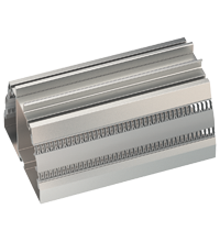
| Mounting | on 35 mm DIN mounting rail acc. to EN 60715:2001 | |
| General information | ||
| Supplementary information | Observe the certificates, declarations of conformity, instruction manuals, and manuals where applicable. For information see www.pepperl-fuchs.com. | |
Classifications
| System | Classcode |
|---|---|
| ECLASS 13.0 | 27210119 |
| ECLASS 12.0 | 27210119 |
| ECLASS 11.0 | 27210119 |
| ECLASS 10.0.1 | 27210119 |
| ECLASS 9.0 | 27210119 |
| ECLASS 8.0 | 27210119 |
| ECLASS 5.1 | 27210119 |
| ETIM 9.0 | EC001485 |
| ETIM 8.0 | EC001485 |
| ETIM 7.0 | EC001485 |
| ETIM 6.0 | EC001485 |
| ETIM 5.0 | EC001485 |
| UNSPSC 12.1 | 32101514 |
Details: KFD2-STC5-2
Function
This signal conditioner provides the galvanic isolation between field circuits and control circuits.
The device supplies 2-wire and 3-wire SMART transmitters, and can also be used with 2-wire SMART current sources.
It transfers the analog input signal as an isolated current value.
Digital signals may be superimposed on the input signal on the field side or on the control side and are transferred bi-directionally.
The device provides a sink mode or a source mode output on the control side terminals.
The device has an internal resistor. Use this resistor if the HART communication resistance in the control circuit is too low.
Test sockets for the connection of HART communicators are integrated into the terminals of the device.
Informative Literature: KFD2-STC5-2
| Literature | Language | File Type | File Size |
|---|---|---|---|
| Application Report - Generating Electricity in Coal-Fired Power Plants | ENG | 412 KB | |
| Application Report - Screening Systems in Sewage Treatment Plants | ENG | 577 KB |
Product Documentation: KFD2-STC5-2
| Safety and Security Documentation | Language | File Type | File Size |
|---|---|---|---|
| Instruction manual | ENG | 41 KB | |
| Functional Safety Manual | ENG | 1974 KB | |
| Manuals | |||
| Manual | ENG | 3685 KB | |
Design / Simulation: KFD2-STC5-2
| CAD | Language | File Type | File Size |
|---|---|---|---|
| CAD 3-D / CAD 3-D | ALL | STP | 3048 KB |
| CAD Portal / CAD Portal | ALL | LINK | --- |
| CAE | |||
| CAE EPLAN Data Portal / CAE EPLAN Data Portal | ALL | LINK | --- |
| CAE EPLAN macro EDZ / CAE EPLAN Makro EDZ | ALL | EDZ | 101 KB |
Approvals: KFD2-STC5-2
| Certificates | Certificate No. | Language | File Type | File Size |
|---|---|---|---|---|
| USA Canada UL Hazardous Location Certificate of Compliance cULus UL E106378 | CoC E106378 RepRef E106378-20171103 | ALL | 413 KB | |
| Declaration of Conformity | ||||
| EU Declaration of Conformity (P+F) / EU-Konformitäterklärung (P+F) | DOC-3647A | ALL | 100 KB | |
| UKCA-Declaration of conformity / UKCA-Konformitätserklärung | DOC-5298 | ALL | 63 KB | |
Associated Products: KFD2-STC5-2
| Matching System Components | ||||||
|---|---|---|---|---|---|---|
|
||||||
|
||||||
|
||||||
|
||||||
|
||||||
|
||||||
| Accessories | ||||||
|
||||||
|
||||||
|
||||||
|
||||||
|
||||||


- Ask an Expert
- Cross Reference Request
- Check order status
- News
- NetPartner Login
- Subscribe to Gate-Way, our Process Automation Division e-newsletter
- Service Level Agreements for ecom instruments
- Find a Local Distributor or Representative
- Literature
- Technologies
- Control System Solutions
- Download Technical Documents
- Press Releases
- International Trade Shows

Choose from various selection criteria like safety integrity level, performance level, device function, and signal type and find the SIL/PL assessed device that you are looking for.


Pepperl+Fuchs Inc.
1600 Enterprise Parkway
Twinsburg, OH 44087
United States of America
sales@us.pepperl-fuchs.com
 +1 330 425-3555
Pepperl+Fuchs is a leading developer and manufacturer of electronic sensors and components for the global automation market. Continuous innovation, enduring quality, and steady growth have been the foundation of our success for more than 70 years. Pepperl+Fuchs employs 6,300 people worldwide and has manufacturing facilities in Germany, USA, Singapore, Hungary, Indonesia and Vietnam, most of them ISO 9001 certified. Pepperl+Fuchs does not sell personal data.