

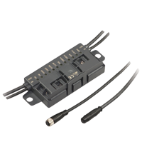
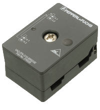
AS-Interface I/O module VBA-4E3A-G20-ZEL/M1L-P6
- A/B node with extended addressing possibility for up to 62 nodes
- Inputs for 3-wire sensors
- Outputs for DC roller motors (drum motors)
- Connection of motors and sensors via M8 connectors
- Configurable start/stop ramps
- Communication monitoring
- Power supply of the inputs and outputs from the external auxiliary voltage
- Function display for bus, external auxiliary voltage, in- and outputs
- Cable piercing method with gold plated contact pins


 Contact Us
Please note: All product-related documents, such as certificates, declarations of conformity, etc., which were issued prior to the conversion under the name Pepperl+Fuchs GmbH or Pepperl+Fuchs AG, also apply to Pepperl+Fuchs SE.
Download the complete datasheet as a PDF:
Datasheet excerpt: Technical data of VBA-4E3A-G20-ZEL/M1L-P6
| Product Description |
|---|
| G20 motor control module for Interroll EC310, Interroll EC5000 24V AI, Rulmeca BL3, Itoh Denki PM500XK, Itoh Denki PM500XC, PULSEROLLER Senergy-IDC |
| General specifications | ||
|---|---|---|
| Node type | A/B node | |
| AS-Interface specification | V3.0 | |
| Required gateway specification | ≥ V2.1 | |
| Profile | S-7.A.E | |
| IO code | 7 | |
| ID code | A | |
| ID1 code | 6 | |
| ID2 code | E | |
| UL File Number | E223772 "For use in NFPA 79 Applications only" | |
| MTBF | 98 a | |
| Compatible roller motors | Interroll EC310, Interroll EC5000 24V AI (20W / 35W / 50W), Rulmeca BL3, Itoh Denki PM500XK, Itoh Denki PM500XC , PULSEROLLER Senergy-IDC | |
| Indicators/operating means | ||
| LED FAULT | error display; LED red red: communication error or address is 0 red flashing: overload of sensor supply or external auxiliary voltage UAUX missing |
|
| LED ERR | Motor fault: 2 LED yellow | |
| LED PWR | AS-Interface voltage; green LED green: voltage OK green flashing: address 0 or sensor supply overload or external auxiliary voltage UAUX missing |
|
| LED AUX | ext. auxiliary voltage UAUX; dual LED green/red green: voltage OK red: reverse voltage |
|
| LED IN | switching state (input); 2 LED yellow | |
| LED FUSE | Motor power supply; 2 green LEDs | |
| LED DIR | Motor rotation direction; yellow LED | |
| LED MOT | Motor active; 2 yellow LEDs | |
| Electrical specifications | ||
| Auxiliary voltage (output) | 18 ... 30 VDC PELV | |
| Rated operating voltage | 26.5 ... 31.6 V from AS-Interface | |
| Rated operating current | ≤ 35 mA | |
| Input | ||
| Number/Type | 2 Inputs for 3-wire sensors (PNP), DC | |
| Supply | from external auxiliary voltage UAUX | |
| Current loading capacity | 500 mA , overload and short-circuit protected | |
| Input current | ≤ 8 mA (limited internally) | |
| Switching point | according to DIN EN 61131-2 0 (undamped) ≤ 0.5 mA 1 (damped) ≥ 2.0 mA |
|
| Signal delay | < 1 ms (input/AS-Interface) | |
| Input filter | 2 ms | |
| Output | ||
| Number/Type | 2 outputs for DC roller motors (MOT1, MOT2) | |
| Supply | from external auxiliary voltage UAUX | |
| Current | 3.5 A continuous current , 5 A (<2 s) , max. 7.5 A (<0,3 s) per motor | |
| Overload protection | Fuse 5 A, I2t = 53.7 A2s per motor | |
| Velocity signal | 1.4 … 13 V at no-load Ri = 5.6 kΩ, RLOAD ≥ 35 kΩ Control via parameter P2:0 |
|
| Rotation direction signal | Off / ≥ (UAUX - 1.0 V) at no-load Ri = 5.6 kΩ, RLOAD ≥ 5 kΩ AS-Interface data bit D2 = 0: UD = Off |
|
| Motor fault | Digital input NPN, U0 = 3.3 V, Ri = 52 kΩ 0 (no error) ≥ 40 µA 1 (error) ≤ 30 µA |
|
| Directive conformity | ||
| Electromagnetic compatibility | ||
| Directive 2014/30/EU | EN 62026-2:2013 | |
| Standard conformity | ||
| Degree of protection | EN 60529:2000 | |
| Fieldbus standard | EN 62026-2:2013 | |
| Input | EN 61131-2:2007 | |
| Emitted interference | EN 61000-6-4:2007 | |
| AS-Interface | EN 62026-2:2013 | |
| Noise immunity | EN 61000-6-2:2005, EN 61326-1:2006, EN 62026-2:2013 | |
| Ambient conditions | ||
| Ambient temperature | -25 ... 60 °C (-13 ... 140 °F) | |
| Storage temperature | -30 ... 85 °C (-22 ... 185 °F) | |
| Mechanical specifications | ||
| Degree of protection | IP54 according to EN 60529 | |
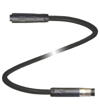
| Connection | AS-Interface, AUX: Insulation piercing technology Yellow flat cable/black flat cable Inputs/outputs: M8 round plug connector in accordance with EN 61076-2-104 Inputs: LF004-GS1-A (4-pin, bushing contacts, screw lock, A-coded) Matching connector: LM004-Gx1-A or similar Outputs: NF005-SS1-B (5-pin, bushing contacts, snap lock, B-coded). Matching connector: NM005-Sx1-B or similar |
|
| Mass | 220 g | |
| Dimensions | ||
| Height | 27.5 mm | |
| Width | 135.5 mm | |
| Length | 54 mm | |
| Mounting | 2 clips with ∅ 8 mm drill hole | |
| Cable length | 0.35 m | |
| Note | The flat cable routing is designed for 100 actuation cycles | |
Classifications
| System | Classcode |
|---|---|
| ECLASS 13.0 | 27242604 |
| ECLASS 12.0 | 27242604 |
| ECLASS 11.0 | 27242604 |
| ECLASS 10.0.1 | 27242604 |
| ECLASS 9.0 | 27242604 |
| ECLASS 8.0 | 27242604 |
| ECLASS 5.1 | 27242604 |
| ETIM 9.0 | EC001599 |
| ETIM 8.0 | EC001599 |
| ETIM 7.0 | EC001599 |
| ETIM 6.0 | EC001599 |
| ETIM 5.0 | EC001599 |
| UNSPSC 12.1 | 39121535 |
Details: VBA-4E3A-G20-ZEL/M1L-P6
Function
The AS-Interface connecting module is a field module with two sensor inputs and two electronic outputs for controlling DC roller motors of the type Interroll EC310 and Rulmeca BL3 or compatible.
The compact housing can be installed directly in support profiles or conduits.
The connection to the AS-Interface network and power supply is made using the AS-Interface flat cable and insulation-piercing technology. The pivoted flat cable guide is secured using a snap fit. No tools are required. The sensor inputs and motor outputs are connected via cable outputs with M8 round plug connectors (inputs 4-pole female cordset with knurled thumb screw, outputs 5-pole snap-on female cordset). Power for the inputs and motors is provided by the external auxiliary voltage UAUX.
The current switching state of the sensor inputs is indicated by the IN LEDs. The FUSE LEDs show that the power supply is applied to both motors. The MOT LEDs indicate when the motors are in operation (stop/operation). The DIR LED indicates the status of the rotation signal. The activation of the fault signal by a motor is displayed with the ERR LEDs.
The motors can be switched on and off individually by means of AS-Interface databits D0 and D1. D2 controls the rotation signal. The AS-Interface parameters P0 ... P2 select the voltage for the speed signal. The rotation and speed apply to both motors.
A start/stop ramp can be set for the speed signal for the controlled acceleration and stopping of the motors. The ramp duration can be selected from eight default values and can be configured over a defined sequence of data and parameters. The ramp selected in this way is saved permanently and is activated automatically after each power-on. The number of the ramp is displayed by a short flash of the ERR2, IN1, and IN2 LEDS in binary code. If the ramp number is set as 0 (no ramp), the six LEDs MOT1 to IN2 flash to show this.
The ramp is not effective if the rotation signal is switched while the motor is running. In other words, the reversal of rotation direction occurs immediately.
Note:
The communication monitor of the module deactivates the outputs if there is no communictaion between the AS-Interface and the module for more than 40 ms.
The IN1 and IN2 inputs suppress impulses of less than than 2 ms.
A signal indicating an overload of the input supply or the absence of the external auxiliary voltage is also transmitted to the AS-Interface master via the "peripheral fault" function. Communication via the AS-Interface continues.
Informative Literature: VBA-4E3A-G20-ZEL/M1L-P6
| Literature | Language | File Type | File Size |
|---|---|---|---|
| Portfolio overview G20 modules / Portfolio-Übersicht G20-Module | ALL | 121 KB |
Product Documentation: VBA-4E3A-G20-ZEL/M1L-P6
| Brief Instructions | Language | File Type | File Size |
|---|---|---|---|
| Instruction leaflet / Beipackzettel | ALL | 225 KB | |
| Manuals | |||
| Manual VBA-4E3A-G20-ZEL/M1L-P2 and VBA-4E3A-G20-ZEL/M1L-P6 | ENG | 944 KB | |
Design / Simulation: VBA-4E3A-G20-ZEL/M1L-P6
| CAD | Language | File Type | File Size |
|---|---|---|---|
| CAD 3-D / CAD 3-D | ALL | STP | 1692 KB |
| CAE | |||
| CAE EPLAN Data Portal / CAE EPLAN Data Portal | ALL | LINK | --- |
| CAE EPLAN macro EDZ / CAE EPLAN Makro EDZ | ALL | EDZ | 41 KB |
Approvals: VBA-4E3A-G20-ZEL/M1L-P6
| Certificates | Certificate No. | Language | File Type | File Size |
|---|---|---|---|---|
| US CA UL AS-Interface | CoC UL-US-L223772-13-82803102-1 | ALL | 175 KB | |
| Worldwide AS-International Association AS-Interface | 96402 | ALL | 124 KB | |
| Declaration of Conformity | ||||
| EU Declaration of Conformity (P+F) / EU-Konformitäterklärung (P+F) | DOC-4822C | ALL | 109 KB | |
Software: VBA-4E3A-G20-ZEL/M1L-P6
| Device Description Files/Drivers | Release Info | File Type | File Size |
|---|---|---|---|
| Add-On Instructions for RSLogix/Studio 5000 / Add-On-Befehle für RSLogix/Studio 5000 | 4/2020 | ZIP | 23385 KB |
Associated Products: VBA-4E3A-G20-ZEL/M1L-P6
| Accessories | ||||||
|---|---|---|---|---|---|---|
|
||||||
|
||||||
|
||||||
|
||||||
|
||||||
|
||||||


This free PDF white paper compares the different TCP-based communication protocols (AMQP, OPC UA, MQTT, REST API) that have found their way up and are considered the enablers of IIoT and Industry 4.0. Get your free download now!
AS-Interface Switch Cabinet Module KE5 – Simple Handling and Improved Manageability
The unique housing design of the new KE5 switch cabinet module enables distinct visibility and simplifies mounting, wiring, and maintenance inside switch cabinets and junction boxes.


Pepperl+Fuchs Inc.
1600 Enterprise Parkway
Twinsburg, OH 44087
United States of America
sales@us.pepperl-fuchs.com
 +1 330 425-3555
Pepperl+Fuchs is a leading developer and manufacturer of electronic sensors and components for the global automation market. Continuous innovation, enduring quality, and steady growth have been the foundation of our success for more than 70 years. Pepperl+Fuchs employs 6,300 people worldwide and has manufacturing facilities in Germany, USA, Singapore, Hungary, Indonesia and Vietnam, most of them ISO 9001 certified. Pepperl+Fuchs does not sell personal data.