

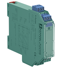
Repeater KFD0-CS-Ex2.52
- 2-channel isolated barrier
- 24 V DC supply (loop powered)
- Current input/output 4 mA ... 20 mA
- Accuracy 0.1 %
- Entity parameter Io/Isc = 0 mA


Quantity

Free Shipping
Purchase on Account

Please note: All product-related documents, such as certificates, declarations of conformity, etc., which were issued prior to the conversion under the name Pepperl+Fuchs GmbH or Pepperl+Fuchs AG, also apply to Pepperl+Fuchs SE.
Download the complete datasheet as a PDF:
Datasheet excerpt: Technical data of KFD0-CS-Ex2.52
| General specifications | ||
|---|---|---|
| Signal type | Analog input | |
| Supply | ||
| Rated voltage | 4 ... 24 V DC , loop powered | |
| Power dissipation | 150 mW | |
| Power consumption | 1 W | |
| Control circuit | ||
| Connection | terminals 12-, 11+; 8-, 10-, 9+ | |
| Voltage | 4 ... 24 V DC for 4 V < Uin < 24 V: 0.97 x Uin - (85 x current in A) - 1.3 | |
| Current | 4 ... 20 mA | |
| Field circuit | ||
| Connection | terminals 1+, 2-; 4+, 5- | |
| Transmission range | current: 4 ... 24 mA voltage: 4 ... 24 V DC |
|
| Transfer characteristics | ||
| Accuracy | 0.1 % | |
| Deviation | ||
| After calibration | ± 20 µA incl. calibration, linearity, hysteresis and load fluctuations at 20 °C (68 °F), Uin ≤ 20 V +20 µA/-50 µA incl. calibration, linearity, hysteresis and load fluctuations at 20 °C (68 °F), 20 V < Uin < 24 V |
|
| Influence of ambient temperature | ± 1 µA/K (0 ... 50 °C (32 ... 122 °F)), Uin ≤ 12 V ± 2 µA/K (0 ... 60 °C (32 ... 140 °F)), Uin ≤ 18 V ± 5 µA/K (-20 ... 60 °C (-4 ... 140 °F)), Uin ≤ 24 V |
|
| Rise time | ≤ 10 ms at 4 ... 20 mA and 250 Ω load | |
| Galvanic isolation | ||
| Input/Output | safe electrical isolation acc. to IEC/EN 60079-11, voltage peak value 375 V | |
| Indicators/settings | ||
| Labeling | space for labeling at the front | |
| Directive conformity | ||
| Electromagnetic compatibility | ||
| Directive 2014/30/EU | EN 61326-1:2013 (industrial locations) | |
| Conformity | ||
| Electromagnetic compatibility | NE 21:2011 | |
| Degree of protection | IEC 60529:2001 | |
| Protection against electrical shock | UL 61010-1:2012 | |
| Ambient conditions | ||
| Ambient temperature | -20 ... 60 °C (-4 ... 140 °F) | |
| Mechanical specifications | ||
| Degree of protection | IP20 | |
| Connection | screw terminals | |
| Mass | approx. 100 g | |
| Dimensions | 20 x 119 x 115 mm (0.8 x 4.7 x 4.5 inch) (W x H x D) , housing type B2 | |
| Height | 119 mm | |
| Width | 20 mm | |
| Depth | 115 mm | |
| Mounting | on 35 mm DIN mounting rail acc. to EN 60715:2001 | |
| Data for application in connection with hazardous areas | ||
| EU-type examination certificate | BASEEFA 03 ATEX 0141 | |
| Marking |  II (1)GD, I (M1) [Ex ia Ga] IIC, [Ex ia Da] IIIC, [Ex ia Ma] I (-20 °C ≤ Tamb ≤ 60 °C) , [circuit(s) in zone 0/1/2] II (1)GD, I (M1) [Ex ia Ga] IIC, [Ex ia Da] IIIC, [Ex ia Ma] I (-20 °C ≤ Tamb ≤ 60 °C) , [circuit(s) in zone 0/1/2] |
|
| Voltage | 25.2 V DC | |
| Current | 0 mA | |
| Output | ||
| Maximum safe voltage | 253 V eff (Attention! The rated voltage can be lower.) | |
| Certificate | TÜV 99 ATEX 1499 X | |
| Marking | II 3G Ex nA II T4 [device in zone 2] |
|
| Galvanic isolation | ||
| Input/Output | safe electrical isolation acc. to IEC/EN 60079-11, voltage peak value 375 V | |
| Directive conformity | ||
| Directive 2014/34/EU | EN IEC 60079-0:2018+AC:2020 , EN 60079-11:2012 , EN 60079-15:2010 | |
| International approvals | ||
| FM approval | ||
| Control drawing | 116-0129 | |
| UL approval | ||
| Control drawing | 116-0173 (cULus) | |
| IECEx approval | ||
| IECEx certificate | IECEx BAS 08.0059 | |
| IECEx marking | [Ex ia Ga] IIC , [Ex ia Da] IIIC , [Ex ia Ma] I | |
| General information | ||
| Supplementary information | Observe the certificates, declarations of conformity, instruction manuals, and manuals where applicable. For information see www.pepperl-fuchs.com. | |
Classifications
| System | Classcode |
|---|---|
| ECLASS 13.0 | 27210123 |
| ECLASS 12.0 | 27210120 |
| ECLASS 11.0 | 27210120 |
| ECLASS 10.0.1 | 27210120 |
| ECLASS 9.0 | 27210120 |
| ECLASS 8.0 | 27210120 |
| ECLASS 5.1 | 27210120 |
| ETIM 9.0 | EC002653 |
| ETIM 8.0 | EC002653 |
| ETIM 7.0 | EC002653 |
| ETIM 6.0 | EC002653 |
| ETIM 5.0 | EC001485 |
| UNSPSC 12.1 | 32101514 |
Details: KFD0-CS-Ex2.52
Function
This isolated barrier is used for intrinsic safety applications. It is loop-powered and repeats a 4 mA ... 20 mA signal from a current source inside a hazardous area to the safe area (It does not provide power for transmitters inside the hazardous area.).
The 25.2 V, 0 mA entity parameters make it easy to design intrinsically safe systems.
Informative Literature: KFD0-CS-Ex2.52
| Literature | Language | File Type | File Size |
|---|---|---|---|
| Application Report - Energy Generation in Wastwater Treatment Plants | ENG | 532 KB | |
| Application Report - Generating Electricity in Coal-Fired Power Plants | ENG | 412 KB | |
| Application Report - Screening Systems in Sewage Treatment Plants | ENG | 577 KB | |
| Application Report - Sicherer Brennstofftransport in Kohlekraftwerken | ENG | 391 KB | |
| Application Report - Water Inlet in Wastewater Treatment Plants | ENG | 526 KB |
Product Documentation: KFD0-CS-Ex2.52
| Safety and Security Documentation | Language | File Type | File Size |
|---|---|---|---|
| Instruction manual | ENG | 50 KB | |
| Manuals | |||
| Manual | ENG | 3685 KB | |
Design / Simulation: KFD0-CS-Ex2.52
| CAD | Language | File Type | File Size |
|---|---|---|---|
| CAD 3-D / CAD 3-D | ALL | STP | 2510 KB |
| CAD Portal / CAD Portal | ALL | LINK | --- |
| CAE | |||
| CAE EPLAN Data Portal / CAE EPLAN Data Portal | ALL | LINK | --- |
| CAE EPLAN macro EDZ / CAE EPLAN Makro EDZ | ALL | EDZ | 1366 KB |
Approvals: KFD0-CS-Ex2.52
| Certificates | Certificate No. | Language | File Type | File Size |
|---|---|---|---|---|
| Baseefa IECEx Certificate of Conformity | IECEx BAS 08.0059 | ALL | LINK | --- |
| Canada FM | FM 18 CA 0098X | ALL | 301 KB | |
| DNV Marine | TAA00001WX | ALL | 106 KB | |
| Europe Baseefa II (1) D I (M1) II (1) G | Baseefa 03 ATEX 0141 | ALL | 4958 KB | |
| Europe TUV Nord ATEX Category 3 G | TÜV 99 ATEX 1499X | ALL | 1999 KB | |
| South Africa MASC | MASC MS/17-0860 | ALL | 606 KB | |
| USA Canada UL Hazardous Location Certificate of Compliance cULus UL E106378 | CoC 20140902 - E106378 RepRef 20011030 | ALL | 429 KB | |
| USA FM | FM 18 US 0207X | ALL | 300 KB | |
| Ukraine SERTIS Ex | SC 21.0646 X | ALL | 12351 KB | |
| Control Drawings | ||||
| Control drawing UL / Control drawing UL | ALL | 1092 KB | ||
| Control drawing FM / Control drawing FM | ALL | 58 KB | ||
| Declaration of Conformity | ||||
| EU Declaration of Conformity (P+F) / EU-Konformitäterklärung (P+F) | DOC-0049C | ALL | 54 KB | |
Associated Products: KFD0-CS-Ex2.52
| Matching System Components | ||||||
|---|---|---|---|---|---|---|
|
||||||
| Accessories | ||||||
|
||||||
|
||||||
|
||||||

 Contact Us


- Ask an Expert
- Cross Reference Request
- Check order status
- News
- NetPartner Login
- Subscribe to Gate-Way, our Process Automation Division e-newsletter
- Service Level Agreements for ecom instruments
- Find a Local Distributor or Representative
- Literature
- Technologies
- Control System Solutions
- Download Technical Documents
- Press Releases
- International Trade Shows

Choose from various selection criteria like safety integrity level, performance level, device function, and signal type and find the SIL/PL assessed device that you are looking for.


Pepperl+Fuchs Inc.
1600 Enterprise Parkway
Twinsburg, OH 44087
United States of America
sales@us.pepperl-fuchs.com
 +1 330 425-3555
Pepperl+Fuchs is a leading developer and manufacturer of electronic sensors and components for the global automation market. Continuous innovation, enduring quality, and steady growth have been the foundation of our success for more than 70 years. Pepperl+Fuchs employs 6,300 people worldwide and has manufacturing facilities in Germany, USA, Singapore, Hungary, Indonesia and Vietnam, most of them ISO 9001 certified. Pepperl+Fuchs does not sell personal data.