| Variants |
|
|
|
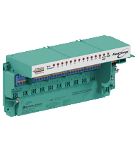
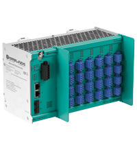
Multi-Input/Output Device for Cabinet Installation, For discrete inputs and outputs, Installation in Zone 1/Div. 1, intrinsically safe, Sensors in Zone 0/Div. 1, Connection to fieldbus acc. to FISCO or Entity, For PROFIBUS PA, IECEx approval, Dust protection, International, Europe, USA, Canada, Device coupler location: non-explosion hazardous area
Zone 2 - high-power trunk
Zone 1 - high-power trunk
Zone 1/2 - intrinsically safe high-power trunk
Zone 1 - intrinsically safe trunkpa |
|
|
|
|
|
Multi-Input/Output Device for Cabinet Installation, For discrete inputs and outputs, Installation in Zone 1/Div. 1, intrinsically safe, Sensors in Zone 0/Div. 1, Connection to fieldbus acc. to FISCO or Entity, For PROFIBUS PA, IECEx approval, Dust protection, International, Europe, USA, Canada, Device coupler location: non-explosion hazardous area
Zone 2 - high-power trunk
Zone 1 - high-power trunk
Zone 1/2 - intrinsically safe high-power trunk
Zone 1 - intrinsically safe trunkpa |
|
| Matching System Components |
|
|
|
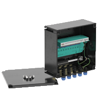
For discrete inputs and outputs, Glass fiber reinforced polyester, impact resistant, IP66, Configurable cable entries for bus lines and field signal lines, International approvals, For PROFIBUS PA, Device coupler location: non-explosion hazardous area
Zone 2 - high-power trunk
Zone 1 - high-power trunk
Zone 1/2 - intrinsically safe high-power trunk
Zone 1 - intrinsically safe trunk, Device coupler location [2]: Zone 2 - high-power trunk, Device coupler location [3]: Zone 1 - high-power trunkpa |
|
|
|
|
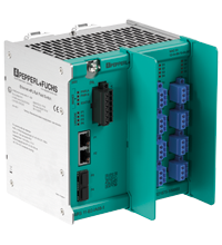
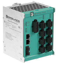
| Ethernet-APL rail field switch with 8 intrinsically safe Ex ia spur ports and screw terminals with proxy support selectable for PROFIBUS PA field devices, Managed Ethernet-APL field switch for process industries, Powered spur ports intrinsically safe Ex ia according to 2-WISE and FISCO, PROFINET MRP, S2 redundancy and dynamic reconfiguration, 2 ports each for 1000BASE-T and SFP transceivers, Redundant power input 20 VDC ... 60 VDC, IECEx approval, International, Europepa |
|
|
|
|
|
| Ethernet-APL rail field switch with 8 intrinsically safe Ex ia spur ports and spring terminals with proxy support selectable for PROFIBUS PA field devices, Managed Ethernet-APL field switch for process industries, Powered spur ports intrinsically safe Ex ia according to 2-WISE and FISCO, PROFINET MRP, S2 redundancy and dynamic reconfiguration, 2 ports each for 1000BASE-T and SFP transceivers, Redundant power input 20 VDC ... 60 VDC, IECEx approval, International, Europepa |
|
|
|
|
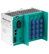
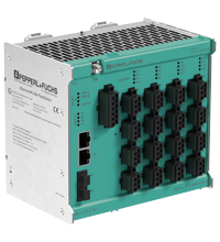
| Ethernet-APL rail field switch with 16 intrinsically safe Ex ia spur ports and screw terminals with proxy support selectable for PROFIBUS PA field devices, Managed Ethernet-APL field switch for process industries, Powered spur ports intrinsically safe Ex ia according to 2-WISE and FISCO, PROFINET MRP, S2 redundancy and dynamic reconfiguration, 2 ports each for 1000BASE-T and SFP transceivers, Redundant power input 20 VDC ... 60 VDC, IECEx approval, International, Europepa |
|
|
|
|
|
| Ethernet-APL rail field switch with 16 intrinsically safe Ex ia spur ports and spring terminals with proxy support selectable for PROFIBUS PA field devices, Managed Ethernet-APL field switch for process industries, Powered spur ports intrinsically safe Ex ia according to 2-WISE and FISCO, PROFINET MRP, S2 redundancy and dynamic reconfiguration, 2 ports each for 1000BASE-T and SFP transceivers, Redundant power input 20 VDC ... 60 VDC, IECEx approval, International, Europepa |
|
|
|
|
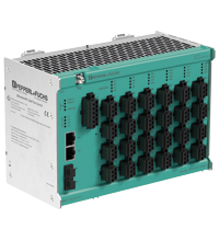
| Ethernet-APL rail field switch with 24 intrinsically safe Ex ia spur ports and screw terminals with proxy support selectable for PROFIBUS PA field devices, Managed Ethernet-APL field switch for process industries, Powered spur ports intrinsically safe Ex ia according to 2-WISE and FISCO, PROFINET MRP, S2 redundancy and dynamic reconfiguration, 2 ports each for 1000BASE-T and SFP transceivers, Redundant power input 20 VDC ... 60 VDC, IECEx approval, International, Europepa |
|
|
|
|
|
| Ethernet-APL rail field switch with 24 intrinsically safe Ex ia spur ports and spring terminals with proxy support selectable for PROFIBUS PA field devices, Managed Ethernet-APL field switch for process industries, Powered spur ports intrinsically safe Ex ia according to 2-WISE and FISCO, PROFINET MRP, S2 redundancy and dynamic reconfiguration, 2 ports each for 1000BASE-T and SFP transceivers, Redundant power input 20 VDC ... 60 VDC, IECEx approval, International, Europepa |
|
|
|
|
| Ethernet-APL rail field switch with 8 intrinsically safe Ex ic spur ports and screw terminals with proxy support selectable for PROFIBUS PA field devices, Managed Ethernet-APL field switch for process industries, Powered spur ports intrinsically safe Ex ic according to 2-WISE and FISCO, PROFINET MRP, S2 redundancy and dynamic reconfiguration, 2 ports each for 1000BASE-T and SFP transceivers, Redundant power input 20 VDC ... 60 VDC, IECEx approval, International, Europepa |
|
|
|
|
|
| Ethernet-APL rail field switch with 8 intrinsically safe Ex ic spur ports and spring terminals with proxy support selectable for PROFIBUS PA field devices, Managed Ethernet-APL field switch for process industries, Powered spur ports intrinsically safe Ex ic according to 2-WISE and FISCO, PROFINET MRP, S2 redundancy and dynamic reconfiguration, 2 ports each for 1000BASE-T and SFP transceivers, Redundant power input 20 VDC ... 60 VDC, IECEx approval, International, Europepa |
|
|
|
|
| Ethernet-APL rail field switch with 16 intrinsically safe Ex ic spur ports and screw terminals with proxy support selectable for PROFIBUS PA field devices, Managed Ethernet-APL field switch for process industries, Powered spur ports intrinsically safe Ex ic according to 2-WISE and FISCO, PROFINET MRP, S2 redundancy and dynamic reconfiguration, 2 ports each for 1000BASE-T and SFP transceivers, Redundant power input 20 VDC ... 60 VDC, IECEx approval, International, Europepa |
|
|
|
|
|
| Ethernet-APL rail field switch with 16 intrinsically safe Ex ic spur ports and spring terminals with proxy support selectable for PROFIBUS PA field devices, Managed Ethernet-APL field switch for process industries, Powered spur ports intrinsically safe Ex ic according to 2-WISE and FISCO, PROFINET MRP, S2 redundancy and dynamic reconfiguration, 2 ports each for 1000BASE-T and SFP transceivers, Redundant power input 20 VDC ... 60 VDC, IECEx approval, International, Europepa |
|
|
|
|
| Ethernet-APL rail field switch with 24 intrinsically safe Ex ic spur ports and screw terminals with proxy support selectable for PROFIBUS PA field devices, Managed Ethernet-APL field switch for process industries, Powered spur ports intrinsically safe Ex ic according to 2-WISE and FISCO, PROFINET MRP, S2 redundancy and dynamic reconfiguration, 2 ports each for 1000BASE-T and SFP transceivers, Redundant power input 20 VDC ... 60 VDC, IECEx approval, International, Europepa |
|
|
|
|
|
| Ethernet-APL rail field switch with 24 intrinsically safe Ex ic spur ports and spring terminals with proxy support selectable for PROFIBUS PA field devices, Managed Ethernet-APL field switch for process industries, Powered spur ports intrinsically safe Ex ic according to 2-WISE and FISCO, PROFINET MRP, S2 redundancy and dynamic reconfiguration, 2 ports each for 1000BASE-T and SFP transceivers, Redundant power input 20 VDC ... 60 VDC, IECEx approval, International, Europepa |
|
| Accessories |

|
|
|
| User interface for PROFIBUS components, Simple access to measurements, diagnostic and configuration data, Supports any FDT/DTM hostpa |
|

|
|
|
| Software for connecting people, information, systems, and devices, For applications developed using .NET, Required to run PACTwarepa |
|

|
|
|
| Universal DTM host platform, For all DTMs of Pepperl+Fuchs, Approved FDT/DTM technology, Free of charge, Download from Pepperl+Fuchs websitepa |
|
|
|
|
|
| Universal DTM host platform, For all DTMs of Pepperl+Fuchs, Approved FDT/DTM technology, Free of charge, Internet download possiblepa |
|


 Contact Us
 II 2 (1) G Ex ib [ia Ga] IIC T4 Gb ,


 +1 330 425-3555