


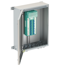
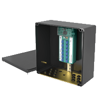
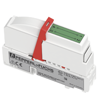
FieldBarrier® for Cabinet Installation R4D0-FB-IA*
- 8 ... 12 outputs Ex ia IIC, FISCO and Entity
- Advanced fault isolation and diagnostics at the spur
- FieldBarrier in Zone 1/Div. 2
- Instruments in Zone 0...1/Div. 1
- For FOUNDATION Fieldbus H1 and PROFIBUS PA
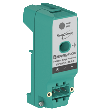
- Supports plug-in surge protectors
- Very compact, small footprint
- Designed for high reliability


 Contact Us
Please note: All product-related documents, such as certificates, declarations of conformity, etc., which were issued prior to the conversion under the name Pepperl+Fuchs GmbH or Pepperl+Fuchs AG, also apply to Pepperl+Fuchs SE.
Download the complete datasheet as a PDF:
Datasheet excerpt: Technical data of R4D0-FB-IA*
| Product Description |
|---|
| FieldConnex® FieldBarrier® |
| General specifications | ||
|---|---|---|
| Design / Mounting | Cabinet installation | |
| Fieldbus connection | ||
| Power dissipation | see table 1 | |
| Main cable (Trunk) | ||
| Rated voltage | 16 ... 32 V DC , min. 15 V in case of brown out |
|
| Rated current | trunk IN to trunk OUT max. 2 A see table 1 |
|
| Cable shield grounding option | Capacitive via 5.7 nF Direct |
|
| Voltage drop | trunk IN to trunk OUT 100 mV max. | |
| Number of couplers | max. 3 per segment | |
| Reverse polarity protection | Built-In | |
| Outputs | ||
| Number of outputs | 8, 10 or 12 | |
| Number of devices per output | 1 | |
| Cable length | 120 m | |
| Rated voltage | 10 ... 14 V | |
| Rated current | max. 43 mA at one spur , max. 320 mA total current at all spurs |
|
| Short-circuit current | 53 mA , 1 mA in fallback state | |
| Cable shield grounding option | Capacitive via 4.4 nF | |
| Surge protection | Trunk overvoltage protection if voltage exceeds typ. 39 V, max. 41 V | |
| Diagnostic and Protection Features | ||
| Fault Isolation | Short Circuit Current Limitation at spurs Bounce Protection at spurs Signal inhibit at spurs |
|
| Physical Layer Diagnostic | Signal level at spurs Signal jitter at spurs Noise level at spurs |
|
| Indicators/operating means | ||
| Switch | S1 ON: diagnostic alarms activated S2 ON: diagnostic warnings activated S3-S8: not used |
|
| LED PWR | green: Fieldbus voltage > 16 V | |
| LED COM/ERR | yellow flashing: fieldbus communication and physical layer status , red: Hardware error |
|
| LED SPURS | red: 2 Hz flashing in short-circuit condition | |
| Galvanic isolation | ||
| Main wire/outputs | isolation is not affected by interference according to EN 60079-11, voltage peak value 375 V | |
| Output/Output | No Isolation | |
| Directive conformity | ||
| Electromagnetic compatibility | ||
| Directive 2014/30/EU | EN 61326-1:2013 | |
| Standard conformity | ||
| Electromagnetic compatibility | NE 21:2011 | |
| Degree of protection | IEC/EN 60529 | |
| Fieldbus standard | IEC 61158-2 | |
| Climatic conditions | IEC 60721 | |
| Shock resistance | EN 60068-2-27 | |
| Vibration resistance | EN 60068-2-6 | |
| Ambient conditions | ||
| Ambient temperature | -40 ... 70 °C (-40 ... 158 °F) | |
| Storage temperature | -40 ... 85 °C (-40 ... 185 °F) | |
| Relative humidity | < 95 % non-condensing | |
| Shock resistance | 15 g 11 ms | |
| Vibration resistance | 1 g , 10 ... 150 Hz | |
| Corrosion resistance | acc. to ISA-S71.04-1985, severity level G3 | |
| Mechanical specifications | ||
| Connection type | pluggable , screw terminal or spring terminal | |
| Core cross section | see table 2 | |
| Housing material | Polycarbonate | |
| Degree of protection | IP20 , IP30 for Ex-e terminal cover |
|
| Mass | 2100 g | |
| Dimensions | see dimensions | |
| Mounting | DIN rail mounting and wall mounting | |
| Data for application in connection with hazardous areas | ||
| EU-type examination certificate | BVS 13 ATEX E 121 X | |
| Marking |  II 2(1)G Ex eb ib mb [ia Ga] IIC T4 Gb II (1)D [Ex ia Da] IIIC I (M1) [Ex ia Ma] I II 2(1)G Ex eb ib mb [ia Ga] IIC T4 Gb II (1)D [Ex ia Da] IIIC I (M1) [Ex ia Ma] I |
|
| Main cable (Trunk) | ||
| Maximum safe voltage | 253 V AC | |
| Outputs | in accordance to FISCO and Entity | |
| Power | 1.063 W | |
| Voltage | 17.1 V | |
| Current | 248.55 mA | |
| Inductance | gas group IIC 470 µH , gas group IIB 2 mH |
|
| Capacitance | gas group IIC 367 nF , gas group IIB 2.15 µF |
|
| Directive conformity | ||
| Directive 2014/34/EU | EN IEC 60079-0:2018+AC:2020 , EN 60079-7:2015+A1:2018 , EN 60079-11:2012 , EN 60079-18:2015 | |
| International approvals | ||
| CSA approval | CSA 14.70004139 | |
| Control drawing | 116-0400 | |
| Approved for | Class I, Division 2, Groups A, B, C, D T4 Class I, Zone 1, AEx/Ex e ib mb [ia Ga] IIC T4 Gb Class I, Zone 1, AEx/Ex e ib mb [ia IIC Da] IIC T4 Gb Associated equipment for Class I, Division 1 Groups A, B, C, D Associated equipment for Class II, Division 1 Groups E, F, G Associated equipment for Class III, Division 1 |
|
| IECEx approval | IECEx BVS 13.0119X | |
| Approved for | Ex eb ib mb [ia Ga] IIC T4 Gb [Ex ia Da] IIIC [Ex ia Ma] I |
|
| Certificates and approvals | ||
| FOUNDATION Fieldbus | FF-846 | |
| General information | ||
| Supplementary information | EC-Type Examination Certificate, Statement of Conformity, Declaration of Conformity, Attestation of Conformity and instructions have to be observed where applicable. For information see www.pepperl-fuchs.com. | |
Classifications
| System | Classcode |
|---|---|
| ECLASS 13.0 | 27242610 |
| ECLASS 12.0 | 27242610 |
| ECLASS 11.0 | 27242610 |
| ECLASS 10.0.1 | 27242610 |
| ECLASS 9.0 | 27242610 |
| ECLASS 8.0 | 27242610 |
| ECLASS 5.1 | 27242610 |
| ETIM 9.0 | EC001601 |
| ETIM 8.0 | EC001601 |
| ETIM 7.0 | EC001601 |
| ETIM 6.0 | EC001601 |
| ETIM 5.0 | EC001604 |
| UNSPSC 12.1 | 39121008 |
Details: R4D0-FB-IA*
Function
The FieldBarrier is a diagnostic-enabled, isolated device coupler for DIN rail mounting and connects 8 … 12 instruments with intrinsic safety. At the spur, advanced fault protection isolates conditions such as short circuit, jabber, or bounce. Advanced Diagnostics at the spur detect installation quality issues for optimum segment availability.
Internal components such as the terminator are connected without wiring. Connections requiring maintenance are minimized. Critical components are designed with redundancy or monitored for degradation. All attributes ensure high product integrity.
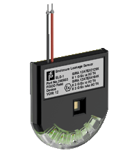
The FieldBarrier supports diagnostic-enabled accessories such as enclosure leakage sensors and surge protectors. They all transmit fault and diagnostic information to the control room indicating the affected spur. All features contribute to simplified installation, troubleshooting and increased plant up-time.
Informative Literature: R4D0-FB-IA*
| Literature | Language | File Type | File Size |
|---|---|---|---|
| Application Report - Controlling and Monitoring liquid Helium at the Deutsches Elektronen-Synchrotron | ENG | 361 KB | |
| Application Report - Digital Communication in Steel-Plate Manufacturing | ENG | 470 KB |
Product Documentation: R4D0-FB-IA*
| Safety and Security Documentation | Language | File Type | File Size |
|---|---|---|---|
| Instruction manual | ENG | 235 KB | |
| Manuals | |||
| Manual | ENG | 2866 KB | |
Design / Simulation: R4D0-FB-IA*
| CAD | Language | File Type | File Size |
|---|---|---|---|
| CAD 2-D / CAD 2-D | ALL | ZIP | 1304 KB |
Approvals: R4D0-FB-IA*
| Certificates | Certificate No. | Language | File Type | File Size |
|---|---|---|---|---|
| BVS IECEx Certificate of Conformity | IECEx BVS 13.0119X | ALL | LINK | --- |
| Brasil TUV Rheinland Brazil | TÜV 14.1591 X | ALL | 1182 KB | |
| Canada, USA CSA Certificate of Compliance | CSA 14.70004139 | ALL | 323 KB | |
| China NEPSI | GYJ16.1473X | ALL | 1853 KB | |
| China SITIIAS CCC Ex Certificate | 2020322316002483 (Singapore) | ALL | 1013 KB | |
| DNV Marine | TAA0000272 | ALL | 100 KB | |
| Europe BVS ATEX Category 2 (1) | BVS 13 ATEX E 121 X | ALL | 1469 KB | |
| South Africa MASC | MASC MS/23-8422X | ALL | 630 KB | |
| United Kingdom CML UK-Type Examination Certificate UKEX Category (1) D UKEX Category (1) G UKEX Category (M1) | CML 23UKEX2145X | ALL | 181 KB | |
| Worldwide Fieldbus Foundation | DC090100 | ALL | 55 KB | |
| Control Drawings | ||||
| Control drawing CSA / Control drawing CSA | ALL | 343 KB | ||
| Declaration of Conformity | ||||
| EU Declaration of Conformity (P+F) | TDOC-0268EENG | ENG | 1142 KB | |
Associated Products: R4D0-FB-IA*
| Matching System Components | ||||||
|---|---|---|---|---|---|---|
|
||||||
|
||||||
| Accessories | ||||||
|
||||||
|
||||||
|
||||||
|
||||||
|
||||||

- Ask an Expert
- Cross Reference Request
- Check order status
- News
- NetPartner Login
- Subscribe to Gate-Way, our Process Automation Division e-newsletter
- Service Level Agreements for ecom instruments
- Find a Local Distributor or Representative
- Literature
- Technologies
- Control System Solutions
- Download Technical Documents
- Press Releases
- International Trade Shows


Pepperl+Fuchs Inc.
1600 Enterprise Parkway
Twinsburg, OH 44087
United States of America
sales@us.pepperl-fuchs.com
 +1 330 425-3555
Pepperl+Fuchs is a leading developer and manufacturer of electronic sensors and components for the global automation market. Continuous innovation, enduring quality, and steady growth have been the foundation of our success for more than 70 years. Pepperl+Fuchs employs 6,300 people worldwide and has manufacturing facilities in Germany, USA, Singapore, Hungary, Indonesia and Vietnam, most of them ISO 9001 certified. Pepperl+Fuchs does not sell personal data.