

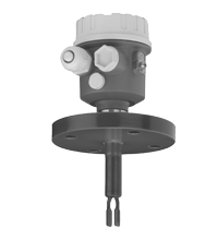
Vibration Limit Switch LVL-M2C
- Limit switch for liquids
- Corrosion resistant coating (HALAR): ideally suited for the process
- Large selection of process connections: universal use
- Wide variety of electronic modules (e. g., relay, thyristor signal output): the right connection for every process control system
- No calibration: quick and low-cost start up
- No mechanically moving parts: maintenance-free, no wear, long operating life
- Monitoring of the vibrating fork for damage: guaranteed function
- PROFIBUS PA protocol: commissioning and maintenance quick and easy
- Up to SIL 2 acc. to IEC/EN 61508


 Contact Us
Please note: All product-related documents, such as certificates, declarations of conformity, etc., which were issued prior to the conversion under the name Pepperl+Fuchs GmbH or Pepperl+Fuchs AG, also apply to Pepperl+Fuchs SE.
Download the complete datasheet as a PDF:
Datasheet excerpt: Technical data of LVL-M2C
| General specifications | ||
|---|---|---|
| Function principle | limit detection Maximum or minimum detection in tanks or pipelines containing all types of liquids including use in explosion hazardous areas. Particularly suited to very aggressive liquids thanks to high degree of corrosion protection. |
|
| Measuring method | The forks of the sensors vibrate at their intrinsic frequency. This frequency is reduced when covered with liquid. The change in frequency then activates the limit switch. |
|
| Construction type | device with extension tube, coated with ECTFE | |
| Series | LVL-M* | |
| Functional safety related parameters | ||
| Safety Integrity Level (SIL) | SIL 2 | |
| Supply | ||
| Rated voltage | electronic insert FEL50A (PA): 9 ... 32 V DC electronic insert FEL51 (AC): 253 V AC, 50/60 Hz electronic insert FEL52 (E5): 10 ... 55 V DC electronic insert FEL54 (WA): 19 ... 253 V AC, 50/60 Hz or 19 ... 55 V DC electronic insert FEL55 (SI): 11 ... 36 V DC, PLC electronic insert FEL56 (N1), FEL58 (N2): isolating amplifier acc. to EN 60947-5-6 (NAMUR) |
|
| Current consumption | electronic insert FEL52 (E5): max. 15 mA | |
| Power consumption | electronic insert FEL52 (E5): max. 0.83 W electronic insert FEL54 (WA): max. 1.3 W |
|
| Electrical specifications | ||
| Surge protection | electronic insert FEL51 (AC), electronic insert FEL52 (E5), electronic insert FEL54 (WA), electronic insert FEL55 (SI): overvoltage category III | |
| Input | ||
| Switching point | see section switch point | |
| Measured variable | limit level (limit value) | |
| Measurement range | depends on mounting point and pipe extension up to 3000 mm , larger sizes on request | |
| Output | ||
| Switching delay | when fork is covered: approx. 0.5 s, when fork is exposed: approx. 1.0 s (other switching times on request) additionally configurable for PROFIBUS PA (electronic insert FEL50A (PA)): 0.5 ... 60 s |
|
| Switch behaviour | switch-over for minimum/maximum residual current safety on electronic insert MAX = maximum safety: The output switches to the power fail response when the fork is covered. for use with overspill protection for example MIN = minimum safety: The output switches to the power fail response when the fork is exposed. for use with dry running protection for example When switching on the power supply the output assumes the alarm signal. After max. 2 s it assumes the correct switching mode. |
|
| Directive conformity | ||
| Electromagnetic compatibility | ||
| Directive 89/336/EEC | EN 61326 If the fork tines are joined together on account of build-up, the useful signal is attenuated to such an extent that the original EMC values can no longer be completely observed (EN 61000-4-3 electromagnetic fields, EN 61000-4-6 HF coupling). |
|
| Low voltage | ||
| Directive 73/23/EEC | EN 61010-1 | |
| Conformity | ||
| Electromagnetic compatibility | NE 21 | |
| Degree of protection | IEC 60529 | |
| Vibration resistance | EN 60068-2-6 | |
| Climate class | DIN EN 60068-2-38/IEC 68-2-38 | |
| Measurement accuracy | ||
| Reference operating conditions | ambient temperature: 23 °C (73.4 °F), medium temperature: 23 °C (73.4 °F), product density: 1 g/cm3 (water), viscosity: 1 mm2/s, medium pressure pe: 0 bar, sensor mounting: vertical from above, density switch: to > 0.7 g/cm3 |
|
| Maximum measured error | max. ± 1 mm, specified by mounting position | |
| Non-repeatability | 0.1 mm | |
| Hysteresis | approx. 2 mm | |
| Influence of medium density | max. +4.8 ... -3.5 mm (0.5 ... 1.5 g/cm3) | |
| Influence of medium temperature | max. 1.4 ... -2.8 mm (-40 ... 120 °C (-40 ... 248 °F)) | |
| Influence of medium pressure | max. 0 ... -2 mm (0 ... 40 bar) | |
| Operating conditions | ||
| Installation conditions | ||
| Installation position | with short pipe (up to 500 mm (19.7 inch)) any position, with long pipe vertical | |
| Process conditions | ||
| Medium temperature | -50 ... 150 °C (-58 ... 302 °F) , exceptions see process connections | |
| Medium pressure | pe = -1 ... 40 bar (-14.5 ... 580.2 psi) over the entire temperature range , exceptions see process connections | |
| Test pressure | max. 100 bar (1.5 times the medium pressure pe), no function during test pressure, burst pressure of diaphragm 200 bar | |
| Pressure surge | max. 20 bar/s | |
| Thermal shock resistance | max. 120 °C/s | |
| State of aggregation | liquid | |
| Density | min. 0.5 g/cm3 , other density settings on request | |
| Viscosity | max. 10000 mm2/s | |
| Solid contents | < ∅5 mm | |
| Ambient conditions | ||
| Ambient temperature | -50 ... 70 °C (-58 ... 158 °F) , function with reduced data values see section ambient temperature |
|
| Storage temperature | -50 ... 80 °C (-58 ... 176 °F) | |
| Vibration resistance | 10 ... 50 Hz, 0.15 mm, 100 cycles | |
| Mechanical specifications | ||
| Degree of protection | polyester, steel, and aluminum housing: IP66/IP67 | |
| Connection | electronic inserts: cross section max. 2.5 mm2, lace in end splice in acc. with DIN 46228 ground lead in housing: cross section max. 2.5 mm2 external equipotential bonding: cross section 4 mm2 |
|
| Material | wetted parts: - process connection and extension pipe: 1.4435/316L with ECTFE coating - vibration fork: 1.4435/316L with ECTFE coating housings: - polyester housing: PBT-FR with PBT-FR cover or with PA12 cover with sight glass, cover seal: EPDM - stainless steel housing: 1.4301/304, cover seal: silicone - aluminum housing: EN-AC-AlSi10Mg, plastic-coated, cover seal: EPDM cable gland: polyamide or brass, nickel-plated temperature spacer: 1.4435/316L flameproof bushing: 1.4435/316L |
|
| Surface quality | Ra < 3.2 µm | |
| Mass | 800 g , basic weight: compact version (length type II), electronic insert, plastic housing, without flange, additional weight is dependent on extension tube, housing and process connection process connections: - A3H 1000 g, A5H 1500 g, A6H 2400 g, A6I 3200 g, A8H 4900 g - H35 1400 g, H65 2400 g, H71 1600 g, H75 3200 g, H95 5900 g, HA3 5600 g - J1H 1700 g extension tube, temperature spacer, flameproof bushing: - BK* 900 g/m - CK* 2300 g/100 in - DKA 100 g, DKB 700 g, DKC 800 g |
|
| Dimensions | housing: diameter max. 85 mm, height max. 173 mm temperature separator, flameproof bushing: additional length L 140 mm process connection: length L min. 115 mm extension: any length L from 148 ... 3000 mm, larger sizes on request extension: length type II, for vertical installation from above same switching point as Vibracon LVL2 vibration fork: width 20.6 mm, fork width 6.5 mm, length 25 mm |
|
| Process connection | flanges to EN 1092-1 from DN25, to ANSI B 16.5 from 1 inch, to JIS B 2238 (RF) from DN50 For further information see type code. |
|
| Data for application in connection with hazardous areas | ||
| EU-type examination certificate | see instruction manuals (SI) | |
| International approvals | ||
| FM approval | see control drawings (ZD) | |
| CSA approval | see control drawings (ZD) | |
| IECEx approval | see instruction manuals (SI) | |
| Indication and operation | ||
| Display elements | electronic inserts: - electronic inserts FEL50 A (PA), FEL58 (N2): green LED, yellow LED - electronic inserts FEL51 (AC), FEL52 (E5), FEL54 (WA), FEL55 (SI), FEL56 (N1): green LED, red LED |
|
| Control elements | electronic insert FEL50A (PA): 8 switches for device address setting electronic inserts FEL51 (AC), FEL52 (E5), FEL54 (WA), FEL55 (SI), FEL56 (N1): two switches for fail-safe mode and density change electronic insert FEL58 (N2): two switches for fail-safe mode and density change and one test button interrupts lead |
|
| Certificates and approvals | ||
| Overspill protection | see approval (ZE) | |
| General information | ||
| Supplementary documentation | technical information (TI) manuals, brief instructions (BA, KA) instruction manuals (SI) control drawings (ZD) |
|
| Supplementary information | EC-Type Examination Certificate, Statement of Conformity, Declaration of Conformity, Attestation of Conformity and instructions have to be observed where applicable. For information see www.pepperl-fuchs.com. | |
| Accessories | ||
| Designation | see technical information (TI) | |
Classifications
| System | Classcode |
|---|---|
| ECLASS 13.0 | 27200518 |
| ECLASS 12.0 | 27200518 |
| ECLASS 11.0 | 27200518 |
| ECLASS 10.0.1 | 27200518 |
| ECLASS 9.0 | 27200589 |
| ECLASS 8.0 | 27200589 |
| ECLASS 5.1 | 27200589 |
| ETIM 9.0 | EC001447 |
| ETIM 8.0 | EC001447 |
| ETIM 7.0 | EC001447 |
| ETIM 6.0 | EC001447 |
| ETIM 5.0 | EC001447 |
| UNSPSC 12.1 | 41111950 |
Details: LVL-M2C
Function
The device is a limit switch for use in all liquids
-
for temperature from -50 °C to +120 °C
-
for pressures up to 40 bar
-
for viscosities up to 10000 mm 2/s
-
for density up to 0.5 g/cm 3 (other settings available on request)
The function is not affected by flow, turbulence, bubbles, foam, vibration, bulk solids content or build-up, the device is thus the ideal replacement for float switches.
The device is available with extension tube up to 3 m (larger sizes on request).
The coating of all device wetted parts (process connections, extension pipe and vibration fork) is made of synthetic material to ensure it can be used for highly aggressive liquids.
Devices with protection Ex ia and Ex d are available for use in explosion hazardous areas.
Product Documentation: LVL-M2C
| Product information | Language | File Type | File Size |
|---|---|---|---|
| TI0347O, Technical information LVL-M2C | ENG | 813 KB | |
| Brief Instructions | |||
| KA162O, brief instructions LVL-M2C / KA162O, Kurzanleitung LVL-M2C | ALL | 1409 KB | |
| Safety and Security Documentation | |||
| SI00063O, Instruction manual LVL-M** NAMUR | ENG | 460 KB | |
| SI00064O, Instruction manual LVL-M** NAMUR | ENG | 404 KB | |
| SI00113O, Instruction manual LVL-M2C NAMUR | ENG | 386 KB | |
| SI00114O, Instruction manual LVL-M2C NAMUR | ENG | 342 KB | |
| SI00031O, Instruction manual LVL-M** | ENG | 376 KB | |
| SI00182O, Instruction manual LVL-MXX | ENG | 983 KB | |
| SI158O, Instruction manual LVL-M2C PROFIBUS PA / SI158O, Betriebsanleitung LVL-M2C PROFIBUS PA | ALL | 435 KB | |
| Manuals | |||
| BA141O, Manual Electronic insert FEL50 A (PA) | ENG | 680 KB | |
Approvals: LVL-M2C
Software: LVL-M2C
| Device Description Files/Drivers | Release Info | File Type | File Size |
|---|---|---|---|
| GSD / GSD | ZIP | 5 KB |
Associated Products: LVL-M2C
| Accessories | ||||||
|---|---|---|---|---|---|---|
|
||||||
|
||||||


- Ask an Expert
- Cross Reference Request
- Check order status
- News
- NetPartner Login
- Subscribe to Gate-Way, our Process Automation Division e-newsletter
- Service Level Agreements for ecom instruments
- Find a Local Distributor or Representative
- Literature
- Technologies
- Control System Solutions
- Download Technical Documents
- Press Releases
- International Trade Shows

Several hundred products with a SIL/PL assessment, free tools, and brochures in one place: the "Functional Safety Hub" is your starting point when you have to implement safety functions.


Pepperl+Fuchs Inc.
1600 Enterprise Parkway
Twinsburg, OH 44087
United States of America
sales@us.pepperl-fuchs.com
 +1 330 425-3555
Pepperl+Fuchs is a leading developer and manufacturer of electronic sensors and components for the global automation market. Continuous innovation, enduring quality, and steady growth have been the foundation of our success for more than 70 years. Pepperl+Fuchs employs 6,300 people worldwide and has manufacturing facilities in Germany, USA, Singapore, Hungary, Indonesia and Vietnam, most of them ISO 9001 certified. Pepperl+Fuchs does not sell personal data.