

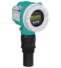
Ultrasonic Level Sensor LUC-M20
- Device for non-contact level measurement
- Measuring range up to 8 m in fluids
- Measuring range up to 3.5 m in bulk materials
- Quick and simple commissioning via menu-guided onsite operation with four-line display
- Optional remote display and operation (up to 20 m from transmitter)
- Integrated temperature sensor for automatic correction of the temperature dependent sound velocity


 Contact Us
Please note: All product-related documents, such as certificates, declarations of conformity, etc., which were issued prior to the conversion under the name Pepperl+Fuchs GmbH or Pepperl+Fuchs AG, also apply to Pepperl+Fuchs SE.
Download the complete datasheet as a PDF:
Datasheet excerpt: Technical data of LUC-M20
| General specifications | ||
|---|---|---|
| Measuring method | The sensor of the device transmits ultrasonic pulses in the direction of the product surface. There, the ultrasonic pulses are reflected back and received by the sensor. The device measures the time between pulse transmission and reception. The instrument uses the time (and the velocity of sound) to calculate the distance between the sensor membrane and the product surface. As the device knows the empty distance from a user entry, the device calculate the level. | |
| Equipment architecture | 4 ... 20 mA output with HART protocol | |
| Construction type | compact device | |
| Series | LUC-M20 | |
| Supply | ||
| Connection | 2-wire , 4 ... 20 mA , HART protocol , 14 ... 30 V DC | |
| Rated voltage | 14 ... 30 V DC , 8 V DC at 20 mA | |
| Ripple | 47 ... 125 Hz , Upp = 200 mV (measured at 500 Ω) | |
| Noise | 0.5 ... 10 kHz , Urms = 2.2 mV (measured at 500 Ω) | |
| Current consumption | 3.6 ... 22 mA | |
| Power consumption | 51 ... 800 mW | |
| Input | ||
| Measured variable | distance between the sensor membrane and the product surface using the linearization function, the device calculate - level in any units - volume in any units - flow across measuring weirs or open channels in any units |
|
| Measurement range | max. 8 m (26.2 foot) in fluids max. 3.5 m (11.5 foot) in bulk materials |
|
| Operating frequency | approx. 50 kHz | |
| Blocking distance | 0.35 m | |
| Output | ||
| Load | min. 250 Ω for HART communication | |
| Linearity | The linearization function of the device allows conversion of the measured value into any unit of length or volume. In open channels or measuring weirs, also a flow linearization is possible (calculation of the flow from the measured level). | |
| Output signal | 4 ... 20 mA with HART protocol | |
| Output damping | 0 ... 255 s , freely selectable | |
| Signal on alarm | error information can be accessed via the following interfaces: - on-site display (error symbol, error code and plain text description) - current output (configurable) - digital interface |
|
| Directive conformity | ||
| Electromagnetic compatibility | ||
| Directive 2014/30/EU | EN 61326-1:2006 , EN 61326-2-3:2006 , EN 61326-2-5:2006 | |
| Low voltage | ||
| Directive 2014/35/EU | EN 61010-1:2001 | |
| Conformity | ||
| Electromagnetic compatibility | NE 21 | |
| Degree of protection | IEC 60529:2001 | |
| Vibration resistance | EN 60068-2-64 | |
| Climate class | EN 60068-2-38 (test Z/AD) DIN/IEC 68 T2-30Db | |
| Resistance to alternating temperature cycles | EN 60068-2-14 | |
| Measurement accuracy | ||
| Reaction time | min. 2 s | |
| Reference operating conditions | temperature = 20 °C (68 °F) pressure = 1013 mbarabs humidity = 50 % ideal reflective surface (e. g. calm, smooth fluid surface) no interference reflections within signal beam set application parameters: - tank shape = flat ceiling - medium property = liquid - process conditions = calm surface |
|
| Measured value resolution | 1 mm | |
| Measuring frequency | max. 0.5 Hz | |
| Maximum measured error | typical specifications for reference operating conditions (include linearity, repeatability, and hysteresis): ± 2 mm (0.08 inch) or 0.2% of set measuring range (empty calibration)1) 1) whichever is greater |
|
| Operating conditions | ||
| Installation conditions | see technical information (TI) | |
| Ambient conditions | ||
| Resistance to alternating temperature cycles | Nb test: +80 °C/- 40 °C (353 K/233 K), 1 K/min, 100 cycles | |
| Vibration resistance | 20 ... 2000 Hz, 1 (m/s2)2/Hz; 3 x 100 min | |
| Process conditions | ||
| Process temperature | -40 ... 80 °C (-40 ... 176 °F) | |
| Process pressure (static pressure) | 0.7 ... 3 bar (10.2 ... 43.5 psi) , absolute pressure | |
| Ambient conditions | ||
| Ambient temperature | -40 ... 80 °C (-40 ... 176 °F) see technical information (TI) |
|
| Storage temperature | -40 ... 80 °C (-40 ... 176 °F) | |
| Mechanical specifications | ||
| Degree of protection | with closed housing, tested according to - IP68, NEMA 6P (24 h at 1.83 m under water surface) - IP66, NEMA 4X with open housing: IP20, NEMA 1 (also ingress protection of the display) |
|
| Connection | cable gland M20x1.5 cable gland NPT1/2 cable gland G1/2 |
|
| Material | material in contact with process: sensor PVDF, seal EPDM housing: aluminum, seawater resistant, chromated, powder-coated cover: - aluminum, for version without on-site display - inspection glass for version with on-site display |
|
| Mass | 2.6 kg | |
| Dimensions | see section dimensions | |
| Process connection | - cylindrical thread G1-1/2B, G2B to DIN/ISO 228/1 - conical thread NPT1-1/2, NPT2 to ANSI B 1.20.1 - flanges to EN 1092-1 from DN80, to ANSI B 16.5 from 3 inch, to JIS B 2238 (RF) from DN80 - mounting bracket LUC-Z17 |
|
| Data for application in connection with hazardous areas | ||
| EU-type examination certificate | see instruction manuals (SI) | |
| Directive conformity | ||
| Directive 2014/34/EU | EN 60079-0:2006 , EN 60079-1:2004 , EN 60079-7:2003 , EN 60079-11:2007 , EN 60079-18:2005 , EN 60079-26:2004 , EN 60079-27:2007 , EN 61241-0:2006 , EN 61241-1:2004+C11:2006 | |
| Mechanical construction | ||
| Construction type | housing design: - F12 housing with sealed terminal compartment for standard or EEx ia applications - T12 housing with separate terminal compartment and flameproof encapsulation cover: - version without on-site display - version with on-site display (transparent cover), this version cannot be supplied together with the ATEX II 1/2D certificate |
|
| Indication and operation | ||
| Display elements | display and operating module LUC-Z15 at the device | |
| Control elements | on-site operation: - via 3 keys of the display and operating module - via handheld terminal remote control: - operation with operating program (for communication variant HART) |
|
| General information | ||
| Supplementary documentation | technical information (TI) manuals, brief instructions (BA, KA) instruction manuals (SI) control drawings (ZD) |
|
| Supplementary information | Observe the certificates, declarations of conformity, instruction manuals, and manuals where applicable. For information see www.pepperl-fuchs.com. | |
| Accessories | ||
| Designation | - LUC-Z19, mounting bracket - LUC-Z2*, cantilever - LUC-Z3*, mounting frame - LUC-Z5*, wall bracket - LUC-Z-A**N**, adapter flange with conical thread - LUC-Z-F**G**, adapter flange with metrical thread - LUC-Z15, display and operating module for on-site operation - LUC-Z16, weather protection cover - LUC-Z40-**1*, remote display and operation |
|
Classifications
| System | Classcode |
|---|---|
| ECLASS 13.0 | 27200506 |
| ECLASS 12.0 | 27200506 |
| ECLASS 11.0 | 27200506 |
| ECLASS 10.0.1 | 27200506 |
| ECLASS 9.0 | 27200506 |
| ECLASS 8.0 | 27200506 |
| ECLASS 5.1 | 27200506 |
| ETIM 9.0 | EC003001 |
| ETIM 8.0 | EC003001 |
| ETIM 7.0 | EC003001 |
| ETIM 6.0 | EC003001 |
| ETIM 5.0 | EC001447 |
| UNSPSC 12.1 | 41111950 |
Details: LUC-M20
Function
The LUC-M20 is a compact measuring device for continuous, non-contact level measurement. The maximum measuring range is 8 m in fluids and 3.5 m in bulk materials. By using the linearisation function, the devcie can also be used for flow measurements in open channels and measuring weirs.
The system integration is ensured via HART (standard), 4 mA ... 20 mA.
Product Documentation: LUC-M20
| Product information | Language | File Type | File Size |
|---|---|---|---|
| TI365O, Technical information LUC-M** | ENG | 2139 KB | |
| Brief Instructions | |||
| KA191O, brief instructions LUC-M**, connection / KA191O, Kurzanleitung LUC-M**, Anschluss | ALL | 95 KB | |
| Manual LUC-M**, Quick setup / Handbuch LUC-M**, Kurzanleitung | ALL | 109 KB | |
| Safety and Security Documentation | |||
| Instruction maunal SI174-C, LUC-M** HART / Betriebsanleitung SI174-C, LUC-M** HART | ALL | 278 KB | |
| SI176O-C, Instruction manual LUC-M** HART, PROFIBUS PA or FOUNDATION Fieldbus with T12 housing / SI176O-C, Betriebsanleitung LUC-M** HART, PROFIBUS PA oder FOUNDATION Fieldbus mit T12-Gehäuse | ALL | 286 KB | |
| SI179O, Instruction manual LUC-M** / SI179O, Betriebsanleitung LUC-M** | ALL | 1361 KB | |
| SI180O-D, Instruction manual LUC-M** PROFIBUS PA, FOUNDATION Fieldbus, HART / SI180O-D, Betriebsanleitung LUC-M** PROFIBUS PA, FOUNDATION Fieldbus, HART | ALL | 289 KB | |
| Manuals | |||
| BA237O, Manual LUC-M HART | ENG | 3175 KB | |
| BA240O, Manual LUC-M | ENG | 5317 KB | |
Approvals: LUC-M20
Software: LUC-M20
| Device Description Files/Drivers | Release Info | File Type | File Size |
|---|---|---|---|
| GSD / GSD | ZIP | 3 KB |
Associated Products: LUC-M20
| Accessories | ||||||
|---|---|---|---|---|---|---|
|
||||||
|
||||||


- Ask an Expert
- Cross Reference Request
- Check order status
- News
- NetPartner Login
- Subscribe to Gate-Way, our Process Automation Division e-newsletter
- Service Level Agreements for ecom instruments
- Find a Local Distributor or Representative
- Literature
- Technologies
- Control System Solutions
- Download Technical Documents
- Press Releases
- International Trade Shows


Pepperl+Fuchs Inc.
1600 Enterprise Parkway
Twinsburg, OH 44087
United States of America
sales@us.pepperl-fuchs.com
 +1 330 425-3555
Pepperl+Fuchs is a leading developer and manufacturer of electronic sensors and components for the global automation market. Continuous innovation, enduring quality, and steady growth have been the foundation of our success for more than 70 years. Pepperl+Fuchs employs 6,300 people worldwide and has manufacturing facilities in Germany, USA, Singapore, Hungary, Indonesia and Vietnam, most of them ISO 9001 certified. Pepperl+Fuchs does not sell personal data.