

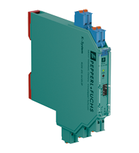
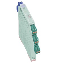
SMART Transmitter Power Supply KCD2-STC-Ex1.ES.SP
- 1-channel isolated barrier
- 24 V DC supply (Power Rail)
- Input for 2-wire SMART transmitters and current sources
- Output for 4 mA ... 20 mA or 1 V ... 5 V
- Sink or source mode
- Line fault detection (LFD)
- Housing width 12.5 mm
- Connection via spring terminals with push-in connection technology
- Up to SIL 3 acc. to IEC/EN 61508


 Contact Us
Please note: All product-related documents, such as certificates, declarations of conformity, etc., which were issued prior to the conversion under the name Pepperl+Fuchs GmbH or Pepperl+Fuchs AG, also apply to Pepperl+Fuchs SE.
Download the complete datasheet as a PDF:
Datasheet excerpt: Technical data of KCD2-STC-Ex1.ES.SP
| General specifications | ||
|---|---|---|
| Signal type | Analog input | |
| Functional safety related parameters | ||
| Safety Integrity Level (SIL) | SIL 3 | |
| Systematic capability (SC) | SC 3 | |
| Supply | ||
| Connection | Power Rail or terminals 9+, 10- | |
| Rated voltage | 19 ... 30 V DC | |
| Ripple | ≤ 10 % | |
| Rated current | ≤ 50 mA | |
| Power dissipation | ≤ 800 mW | |
| Power consumption | ≤ 1.2 W | |
| Input | ||
| Connection side | field side | |
| Connection | terminals 1+, 2-; 3+, 4- | |
| Input signal | 4 ... 20 mA , limited to approx. 27 mA reverse polarity protected | |
| Line fault detection | downscaling ≤ 3 mA ; upscaling ≥ 22 mA | |
| Voltage drop | approx. 5 V on terminals 3+, 4- | |
| Available voltage | ≥ 15 V at 20 mA terminals 1+, 2- | |
| Output | ||
| Connection side | control side | |
| Connection | terminals 5-, 6+ | |
| Load | 0 ... 300 Ω (source mode) | |
| Output signal | source mode: 4 ... 20 mA or 1 ... 5 V (internal resistor: 250 Ω, 0.1 %) sink mode: 4 ... 20 mA, operating voltage 16 ... 28 V For additional internal or external loads the voltage drop has to be considered, e. g. 250 Ω x 20 mA = 5 V. |
|
| Ripple | 20 mV rms | |
| Fault indication output | ||
| Output type | fault bus signal , open collector transistor | |
| Transfer characteristics | ||
| Deviation | at 20 °C (68 °F) ≤ ± 20 µA incl. calibration, linearity, hysteresis, loads and supply voltage fluctuations (source mode and sink mode 4 ... 20 mA) ≤ 10 mV incl. calibration, linearity, hysteresis and fluctuations of supply voltage (source mode 1 ... 5 V) |
|
| Influence of ambient temperature | < 2 µA/K (0 ... 70 °C (32 ... 158 °F)); < 4 µA/K (-20 ... 0 °C (-4 ... 32 °F)) (source mode and sink mode 4 ... 20 mA) < 0.5 mV/K (0 ... 70 °C (32 ... 158 °F)); < 1 mV/K (-20 ... 0 °C (-4 ... 32 °F)) (source mode 1 ... 5 V) |
|
| Frequency range | field side into the control side: bandwidth with 1 mApp signal 0 ... 3 kHz (-3 dB) control side into the field side: bandwidth with 0.5 Vpp signal 0 ... 3 kHz (-3 dB) |
|
| Settling time | ≤ 200 ms | |
| Rise time/fall time | ≤ 20 ms | |
| Galvanic isolation | ||
| Input/Output | safe electrical isolation acc. to IEC/EN 60079-11, voltage peak value 375 V | |
| Input/power supply | safe electrical isolation acc. to IEC/EN 60079-11, voltage peak value 375 V | |
| Output/power supply | Basic isolation acc. to EN 61010-1 rated insulation voltage ≤ 50 V | |
| Indicators/settings | ||
| Display elements | LEDs | |
| Control elements | DIP switch | |
| Factory setting | output: current source | |
| Configuration | via DIP switches | |
| Labeling | space for labeling at the front | |
| Directive conformity | ||
| Electromagnetic compatibility | ||
| Directive 2014/30/EU | EN 61326-1:2013 (industrial locations) | |
| Conformity | ||
| Electromagnetic compatibility | NE 21:2017 For further information see system description. |
|
| Degree of protection | IEC 60529:2001 | |
| Ambient conditions | ||
| Ambient temperature | -20 ... 70 °C (-4 ... 158 °F) | |
| Mechanical specifications | ||
| Degree of protection | IP20 | |
| Connection | spring terminals | |
| Mass | approx. 100 g | |
| Dimensions | 12.5 x 119 x 114 mm (0.5 x 4.7 x 4.5 inch) (W x H x D) , housing type A2 | |
| Height | 124 mm | |
| Width | 12.5 mm | |
| Depth | 114 mm | |
| Mounting | on 35 mm DIN mounting rail acc. to EN 60715:2001 | |
| Data for application in connection with hazardous areas | ||
| EU-type examination certificate | CESI 10 ATEX 071 | |
| Marking |  II (1)G [Ex ia Ga] IIC II (1)D [Ex ia Da] IIIC I (M1) [Ex ia Ma] I II (1)G [Ex ia Ga] IIC II (1)D [Ex ia Da] IIIC I (M1) [Ex ia Ma] I |
|
| Input | Ex ia | |
| Supply | ||
| Maximum safe voltage | 253 V AC (Attention! Um is no rated voltage.) | |
| Equipment | terminals 1+, 2- | |
| Voltage | 25.2 V | |
| Current | 100 mA | |
| Power | 630 mW | |
| Internal capacitance | 5.7 nF | |
| Internal inductance | negligible | |
| Equipment | terminals 3+, 4- | |
| Voltage | < 30 V | |
| Current | < 128 mA | |
| Voltage | 7.2 V | |
| Current | 100 mA | |
| Power | 25 mW | |
| Internal capacitance | 5.7 nF | |
| Internal inductance | negligible | |
| Certificate | CESI 19 ATEX 005 X | |
| Marking | II 3G Ex ec IIC T4 Gc |
|
| Directive conformity | ||
| Directive 2014/34/EU | EN 60079-0:2012+A11:2013 , EN 60079-11:2012 , EN 60079-7:2015 | |
| International approvals | ||
| UL approval | E106378 | |
| Control drawing | 116-0378 (cULus) | |
| IECEx approval | ||
| IECEx certificate | IECEx CES 11.0001X | |
| IECEx marking | [Ex ia Ga] IIC , [Ex ia Da] IIIC , [Ex ia Ma] I Ex ec IIC T4 Gc |
|
| General information | ||
| Supplementary information | Observe the certificates, declarations of conformity, instruction manuals, and manuals where applicable. For information see www.pepperl-fuchs.com. | |
Classifications
| System | Classcode |
|---|---|
| ECLASS 13.0 | 27210119 |
| ECLASS 12.0 | 27210119 |
| ECLASS 11.0 | 27210119 |
| ECLASS 10.0.1 | 27210119 |
| ECLASS 9.0 | 27210119 |
| ECLASS 8.0 | 27210119 |
| ECLASS 5.1 | 27210119 |
| ETIM 9.0 | EC001485 |
| ETIM 8.0 | EC001485 |
| ETIM 7.0 | EC001485 |
| ETIM 6.0 | EC001485 |
| ETIM 5.0 | EC001485 |
| UNSPSC 12.1 | 32101514 |
Details: KCD2-STC-Ex1.ES.SP
Function
This isolated barrier is used for intrinsic safety applications.
The device supplies 2-wire transmitters in the hazardous area, and can also be used with current sources.
The device transfers the analog input signal to the non-hazardous area as an isolated current value.
Bi-directional communication is supported for SMART transmitters that use current modulation to transmit data and voltage modulation to receive data.
The output is selected as a current source, current sink, or voltage source via DIP switches.
A fault is signalized by LEDs and a separate collective error message output.
Test sockets for the connection of HART communicators are integrated into the terminals of the device.
Informative Literature: KCD2-STC-Ex1.ES.SP
| Literature | Language | File Type | File Size |
|---|---|---|---|
| Application Report - Biological Cleaning of Wastwater and Secondary Sedimentation Stage | ENG | 566 KB | |
| Application Report - Energy Generation in Wastwater Treatment Plants | ENG | 532 KB | |
| Application Report - Generating Electricity in Coal-Fired Power Plants | ENG | 412 KB | |
| Application Report - Sand Trap and Preliminary Sedimentation Stage | ENG | 448 KB | |
| Application Report - Screening Systems in Sewage Treatment Plants | ENG | 577 KB | |
| Application Report - Sicherer Brennstofftransport in Kohlekraftwerken | ENG | 391 KB | |
| Application Report - Water Inlet in Wastewater Treatment Plants | ENG | 526 KB |
Product Documentation: KCD2-STC-Ex1.ES.SP
| Safety and Security Documentation | Language | File Type | File Size |
|---|---|---|---|
| Instruction manual | ENG | 169 KB | |
| Safety Manual | ENG | 427 KB | |
| Manuals | |||
| Manual | ENG | 3685 KB | |
Design / Simulation: KCD2-STC-Ex1.ES.SP
| CAD | Language | File Type | File Size |
|---|---|---|---|
| CAD 3-D / CAD 3-D | ALL | STP | 3048 KB |
| CAD Portal / CAD Portal | ALL | LINK | --- |
| CAE | |||
| CAE EPLAN Data Portal / CAE EPLAN Data Portal | ALL | LINK | --- |
| CAE EPLAN macro EDZ / CAE EPLAN Makro EDZ | ALL | EDZ | 1685 KB |
Approvals: KCD2-STC-Ex1.ES.SP
| Certificates | Certificate No. | Language | File Type | File Size |
|---|---|---|---|---|
| China NEPSI | GYJ19.1285 | ALL | 2077 KB | |
| China SITIIAS CCC Ex Certificate | 2020322316001399 (Singapore) | ALL | 1074 KB | |
| Europe CESI ATEX Category 3 G | CESI 19 ATEX 005X | ALL | 400 KB | |
| Europe CESI I (M1) II (1) G II (1) D ATEX Category | CESI 10 ATEX 071 | ALL | 629 KB | |
| India PESO (India) CCOE | A/P/HQ/KA/104/5873 (P507652) | ALL | 101 KB | |
| South Africa MASC | MASC MS/23-8149X | ALL | 642 KB | |
| TÜV SÜD Functional Safety Certificate | C-IS-204399-01 | ALL | 188 KB | |
| USA Canada UL Hazardous Location Certificate of Compliance cULus UL E106378 | CoC E106378 RepRef E106378-20130719 | ALL | 413 KB | |
| Worldwide CESI IECEx Certificate of Conformity | IECEx CES 11.0001X | ALL | LINK | --- |
| Control Drawings | ||||
| Control drawing UL / Control drawing UL | ALL | 128 KB | ||
| Declaration of Conformity | ||||
| EU Declaration of Conformity (P+F) / EU-Konformitäterklärung (P+F) | DOC-0297E | ALL | 82 KB | |
Associated Products: KCD2-STC-Ex1.ES.SP
| Matching System Components | ||||||
|---|---|---|---|---|---|---|
|
||||||
|
||||||
|
||||||
|
||||||
|
||||||
|
||||||
| Accessories | ||||||
|
||||||
|
||||||
|
||||||
|
||||||


- Ask an Expert
- Cross Reference Request
- Check order status
- News
- NetPartner Login
- Subscribe to Gate-Way, our Process Automation Division e-newsletter
- Service Level Agreements for ecom instruments
- Find a Local Distributor or Representative
- Literature
- Technologies
- Control System Solutions
- Download Technical Documents
- Press Releases
- International Trade Shows

Choose from various selection criteria like safety integrity level, performance level, device function, and signal type and find the SIL/PL assessed device that you are looking for.


Pepperl+Fuchs Inc.
1600 Enterprise Parkway
Twinsburg, OH 44087
United States of America
sales@us.pepperl-fuchs.com
 +1 330 425-3555
Pepperl+Fuchs is a leading developer and manufacturer of electronic sensors and components for the global automation market. Continuous innovation, enduring quality, and steady growth have been the foundation of our success for more than 70 years. Pepperl+Fuchs employs 6,300 people worldwide and has manufacturing facilities in Germany, USA, Singapore, Hungary, Indonesia and Vietnam, most of them ISO 9001 certified. Pepperl+Fuchs does not sell personal data.