

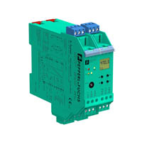
Strain Gauge Converter KFD2-WAC2-Ex1.D-Y189512
- 1-channel isolated barrier
- 24 V DC supply (Power Rail)
- Strain gauge input
- Output 0 mA ... ± 20 mA or 0 V ... ± 10 V
- Relay contact output
- Programmable high/low alarm
- Configurable by PACTware or keypad
- RS 485 interface
- Low response time
- Line fault detection (LFD)


Please note: All product-related documents, such as certificates, declarations of conformity, etc., which were issued prior to the conversion under the name Pepperl+Fuchs GmbH or Pepperl+Fuchs AG, also apply to Pepperl+Fuchs SE.
Download the complete datasheet as a PDF:
Datasheet excerpt: Technical data of KFD2-WAC2-Ex1.D-Y189512
| Product Description |
|---|
| 24 V DC |
| General specifications | ||
|---|---|---|
| Signal type | Analog input | |
| Supply | ||
| Connection | Power Rail or terminals 23+, 24- | |
| Rated voltage | 20 ... 35 V DC | |
| Ripple | within the supply tolerance | |
| Power consumption | max. 3 W | |
| Interface | ||
| Connection | Power Rail or terminals 19+, 20 GND, 21- | |
| Type | RS-485 | |
| Programming interface | RS 232 programming jack | |
| Field circuit | ||
| Connection | terminals 1+, 2-, 3+, 4-, 5+, 6- | |
| Lead resistance | max. 25 Ω per line | |
| Input I | ||
| Connection | terminals 1+, 2- | |
| Sensor supply | 1 ... 5 V | |
| Connection | terminals 3+, 4-, 5+, 6- | |
| Short-circuit current | 50 mA | |
| Load | ≥ 116 Ω up to 5V, ≥ 85 Ω up to 4V | |
| Input | ||
| Connection | Input I: terminals 1+, 2-; Input II: terminals 13+, 14-; Input III: terminals 15+, 14- | |
| Programmable Tare | 0 ... 500 % of span | |
| Input I | Signal, analog | |
| Input signal | -100 ... 100 mV | |
| Input resistance | > 1 MΩ for voltage measurement | |
| Input II, III | tare adjustment, calibration and zero | |
| Open circuit voltage/short-circuit current | 18 V / 5 mA | |
| Active/Passive | I > 4 mA/I < 1.5 mA | |
| Output | ||
| Connection | Output I: terminals 10, 11, 12; Output II: terminals 16, 17, 18; Output III: terminals 7-, 8+, 9- | |
| Output I, II | Relay output | |
| Contact loading | 253 V AC/2 A/500 VA/cos φ min. 0.7; 40 V DC/2 A resistive load | |
| Mechanical life | 2 x 10⁷ switching cycles | |
| Output III | Analog output | |
| Current range | -20 ... 20 mA | |
| Load | max. 550 Ω | |
| Analog voltage output | 0 ... ± 10 V; output resistance 500 Ω (bridge between terminal 7 and 9) | |
| Analog current output | 0 ... ± 20 mA or 4 ... 20 mA; load 0 ... 550 Ω (terminals 7 and 8) | |
| Line fault detection | downscale -21.5 mA (-10.75 V) or 2 mA (1 V), upscale 21.5 mA (10.75 V) | |
| Transfer characteristics | ||
| Deviation | ||
| Resolution/accuracy | ≤ ± 0.2 % incl. non-linearity and hysteresis | |
| Temperature effect | ≤ ± 0.01 %/K | |
| Reaction time | 150 ms | |
| Galvanic isolation | ||
| Output I, II against eachother | reinforced insulation according to IEC 61140, rated insulation voltage 300 Veff | |
| Output I, II/other circuits | reinforced insulation according to IEC 61140, rated insulation voltage 300 Veff | |
| Output III/Input II, III | not available | |
| Output III/Programming socket | not available | |
| Other circuits from each other | functional insulation acc. to IEC 62103, rated insulation voltage 50 Veff | |
| Directive conformity | ||
| Electromagnetic compatibility | ||
| Directive 2004/108/EC | EN 61326-1:2006 | |
| Low voltage | ||
| Directive 2006/95/EC | EN 50178:1997 | |
| Conformity | ||
| Electromagnetic compatibility | NE 21 | |
| Degree of protection | IEC 60529 | |
| Protection against electrical shock | IEC 61140 | |
| Ambient conditions | ||
| Ambient temperature | -20 ... 60 °C (-4 ... 140 °F) | |
| Mechanical specifications | ||
| Degree of protection | IP20 | |
| Mass | approx. 250 g | |
| Dimensions | 40 x 119 x 115 mm (1.6 x 4.7 x 4.5 inch) , housing type C2 | |
| Height | 119 mm | |
| Width | 40 mm | |
| Length | 115 mm | |
| Data for application in connection with hazardous areas | ||
| EU-type examination certificate | TÜV 04 ATEX 2531 , for additional certificates see www.pepperl-fuchs.com | |
| Marking |  II (1)GD [EEx ia] IIC [circuit(s) in zone 0/1/2] II (1)GD [EEx ia] IIC [circuit(s) in zone 0/1/2] |
|
| Supply | Power Rail or terminals 23+, 24- non-intrinsically safe | |
| Maximum safe voltage | 40 V DC (Attention! Um is no rated voltage.) | |
| Input I | terminals 1+, 2- EEx ia IIC | |
| Voltage | 14 V | |
| Current | 238 mA | |
| Power | 833 mW (linear characteristic) | |
| Input II and III | terminals 13+, 14-; 15+, 14- non-intrinsically safe | |
| Maximum safe voltage | 40 V DC (Attention! Um is no rated voltage.) | |
| Output I, II | terminals 10, 11, 12; 16, 17, 18 non-intrinsically safe | |
| Maximum safe voltage | 253 V AC / 40 V DC (Attention! Um is no rated voltage.) | |
| Contact loading | 253 V AC/2 A/500 VA/cos φ min. 0.7; 40 V DC/2 A resistive load | |
| Output III | terminals 7-, 8+, 9- non-intrinsically safe | |
| Maximum safe voltage | 40 V DC (Attention! Um is no rated voltage.) | |
| Interface | RS 485 programming jack | |
| Maximum safe voltage | 40 V DC (Attention! Um is no rated voltage.) | |
| Galvanic isolation | ||
| Input I/other circuits | safe galvanic isolation acc. to EN 50020, voltage peak value 375 V | |
| Directive conformity | ||
| Directive 94/9/EC | EN 50014, EN 50020 | |
| General information | ||
| Supplementary information | EC-Type Examination Certificate, Statement of Conformity, Declaration of Conformity, Attestation of Conformity and instructions have to be observed where applicable. For information see www.pepperl-fuchs.com. | |
Classifications
| System | Classcode |
|---|---|
| ECLASS 13.0 | 27210120 |
| ECLASS 12.0 | 27210190 |
| ECLASS 11.0 | 27210190 |
| ECLASS 10.0.1 | 27210190 |
| ECLASS 9.0 | 27210190 |
| ECLASS 8.0 | 27210190 |
| ECLASS 5.1 | 27210107 |
| ETIM 9.0 | EC002476 |
| ETIM 8.0 | EC002476 |
| ETIM 7.0 | EC002476 |
| ETIM 6.0 | EC002476 |
| ETIM 5.0 | EC001485 |
| UNSPSC 12.1 | 32101514 |
Details: KFD2-WAC2-Ex1.D-Y189512
Product Documentation: KFD2-WAC2-Ex1.D-Y189512
| Brief Instructions | Language | File Type | File Size |
|---|---|---|---|
| Operator card KF**-WAC2-**1.D / Bedienkarte KF**-WAC2-**1.D | ALL | 928 KB | |
| Manuals | |||
| Manual KF**-WAC2-(Ex)1.D | ENG | 1799 KB | |
| Manual | ENG | 3685 KB | |
Design / Simulation: KFD2-WAC2-Ex1.D-Y189512
| CAD | Language | File Type | File Size |
|---|---|---|---|
| CAD 2-D / CAD 2-D | ALL | ZIP | 657 KB |
| CAD 3-D / CAD 3-D | ALL | STP | 870 KB |


Choose from various selection criteria like safety integrity level, performance level, device function, and signal type and find the SIL/PL assessed device that you are looking for.


Pepperl+Fuchs SE
Lilienthalstraße 200
68307 Mannheim
Germany
info@de.pepperl-fuchs.com
 +49 621 776-0
Pepperl+Fuchs is a leading developer and manufacturer of electronic sensors and components for the global automation market. Continuous innovation, enduring quality, and steady growth have been the foundation of our success for more than 70 years. Pepperl+Fuchs employs 6,300 people worldwide and has manufacturing facilities in Germany, USA, Singapore, Hungary, Indonesia and Vietnam, most of them ISO 9001 certified.