

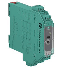
Transmitter Power Supply/Converter KFU8-VCR-1
- 1-channel signal conditioner
- Universal usage at different power supplies
- Input 2-wire and 3-wire transmitters, current and voltage sources
- Current and voltage output

Please note: All product-related documents, such as certificates, declarations of conformity, etc., which were issued prior to the conversion under the name Pepperl+Fuchs GmbH or Pepperl+Fuchs AG, also apply to Pepperl+Fuchs SE.
Download the complete datasheet as a PDF:
Datasheet excerpt: Technical data of KFU8-VCR-1
| General specifications | ||
|---|---|---|
| Signal type | Analog input | |
| Supply | ||
| Connection | terminals 14, 15 | |
| Rated voltage | 19 ... 90 V DC / 48 ... 253 V AC | |
| Rated current | ≤ 110 mA DC / ≤ 75 mA AC | |
| Power dissipation | 1.3 W | |
| Power consumption | 2.1 W | |
| Input | ||
| Connection side | field side | |
| Input I | ||
| Connection | terminals 1+, 2-, 3 | |
| Input signal | 0/4 ... 20 mA | |
| Rated current | 22 mA | |
| Available voltage | > 15 V at 20 mA , terminals 1+, 3- | |
| Open circuit voltage/short-circuit current | 21 V / 26 mA , terminals 1+, 3- terminals 1+, 2- not short-circuit protected |
|
| Input resistance | < 55 Ω , terminals 2-, 3+ | |
| Input II | ||
| Connection | terminals 5-, 6+ | |
| Input signal | 0/2 ... 10 V | |
| Input resistance | > 1 MΩ | |
| Output | ||
| Connection side | control side | |
| Output I | current output | |
| Connection | source: terminals 7(-), 8(+) sink: terminals 7(+), 9(-) |
|
| Output signal | 0/4 ... 20 mA | |
| Source | load 0 ... 750 Ω open circuit voltage < 21 V | |
| Sink | voltage across terminals 5 ... 30 V | |
| Output II | voltage output | |
| Connection | terminals 10-, 11+ | |
| Output signal | 0/2 ... 10 V | |
| Load | min. 10 kΩ | |
| Transfer characteristics | ||
| Deviation | ||
| Resolution/accuracy | S1 in position I: 7 µA/40 µA (0.2 %) S1 in position II: 3.5 mV/20 mV (0.2 %) |
|
| Influence of ambient temperature | 0.01 % / K of output signal range | |
| Reaction time | 150 ms | |
| Galvanic isolation | ||
| Input/Output | functional insulation acc. to IEC 62103, rated insulation voltage 100 Vrms | |
| Input/power supply | reinforced insulation according to IEC/EN 61010-1, rated insulation voltage 300 Veff | |
| Output/power supply | reinforced insulation according to IEC/EN 61010-1, rated insulation voltage 300 Veff | |
| Indicators/settings | ||
| Display elements | LED | |
| Control elements | DIP switch rotary switch |
|
| Configuration | via DIP switches via rotary switch |
|
| Labeling | space for labeling at the front | |
| Directive conformity | ||
| Electromagnetic compatibility | ||
| Directive 2014/30/EU | EN 61326-1:2013 (industrial locations) | |
| Low voltage | ||
| Directive 2014/35/EU | EN 61010-1:2010 | |
| Conformity | ||
| Electromagnetic compatibility | NE 21:2006 | |
| Degree of protection | IEC 60529:1989+A1:1999+A2:2013 | |
| Ambient conditions | ||
| Ambient temperature | -20 ... 60 °C (-4 ... 140 °F) | |
| Mechanical specifications | ||
| Degree of protection | IP20 | |
| Connection | screw terminals | |
| Mass | approx. 150 g | |
| Dimensions | 20 x 119 x 115 mm (0.8 x 4.7 x 4.5 inch) (W x H x D) , housing type B2 | |
| Height | 119 mm | |
| Width | 20 mm | |
| Depth | 115 mm | |
| Mounting | on 35 mm DIN mounting rail acc. to EN 60715:2001 | |
| General information | ||
| Supplementary information | Observe the certificates, declarations of conformity, instruction manuals, and manuals where applicable. For information see www.pepperl-fuchs.com. | |
Classifications
| System | Classcode |
|---|---|
| ECLASS 13.0 | 27210119 |
| ECLASS 12.0 | 27210119 |
| ECLASS 11.0 | 27210119 |
| ECLASS 10.0.1 | 27210119 |
| ECLASS 9.0 | 27210119 |
| ECLASS 8.0 | 27210119 |
| ECLASS 5.1 | 27210119 |
| ETIM 9.0 | EC001485 |
| ETIM 8.0 | EC001485 |
| ETIM 7.0 | EC001485 |
| ETIM 6.0 | EC001485 |
| ETIM 5.0 | EC001485 |
| UNSPSC 12.1 | 32101514 |
Details: KFU8-VCR-1
Function
This signal conditioner provides the isolation for non-intrinsically safe applications.
The device supplies 2-wire and 3-wire transmitters, and can also be used with current and voltage sources.
The input ranges include 0/4 mA ... 20 mA or 0/2 V ... 10 V.
At the output the signal is available as 0/4 mA ... 20 mA or 0/2 V ... 10 V.
Output and measuring range are selected by switches located on the front of the device.
Informative Literature: KFU8-VCR-1
| Literature | Language | File Type | File Size |
|---|---|---|---|
| Application Report - Biological Cleaning of Wastwater and Secondary Sedimentation Stage | ENG | 566 KB | |
| Application Report - Generating Electricity in Coal-Fired Power Plants | ENG | 412 KB | |
| Application Report - Sand Trap and Preliminary Sedimentation Stage | ENG | 448 KB | |
| Application Report - Screening Systems in Sewage Treatment Plants | ENG | 577 KB |
Product Documentation: KFU8-VCR-1
| Safety and Security Documentation | Language | File Type | File Size |
|---|---|---|---|
| Instruction manual | ENG | 41 KB | |
| Manuals | |||
| System Manual | ENG | 3694 KB | |
Design / Simulation: KFU8-VCR-1
| CAD | Language | File Type | File Size |
|---|---|---|---|
| CAD 3-D / CAD 3-D | ALL | STP | 2510 KB |
| CAD Portal / CAD Portal | ALL | LINK | --- |
| CAE | |||
| CAE EPLAN macro EDZ / CAE EPLAN Makro EDZ | ALL | EDZ | 63 KB |
Approvals: KFU8-VCR-1
| Declaration of Conformity | Certificate No. | Language | File Type | File Size |
|---|---|---|---|---|
| EU Declaration of Conformity (P+F) / EU-Konformitäterklärung (P+F) | DOC-3179A | ALL | 373 KB |
Associated Products: KFU8-VCR-1
| Matching System Components | ||||||
|---|---|---|---|---|---|---|
|
||||||
| Accessories | ||||||
|
||||||
|
||||||


Choose from various selection criteria like safety integrity level, performance level, device function, and signal type and find the SIL/PL assessed device that you are looking for.


Pepperl+Fuchs SE
Lilienthalstraße 200
68307 Mannheim
Germany
info@de.pepperl-fuchs.com
 +49 621 776-0
Pepperl+Fuchs is a leading developer and manufacturer of electronic sensors and components for the global automation market. Continuous innovation, enduring quality, and steady growth have been the foundation of our success for more than 70 years. Pepperl+Fuchs employs 6,300 people worldwide and has manufacturing facilities in Germany, USA, Singapore, Hungary, Indonesia and Vietnam, most of them ISO 9001 certified.