

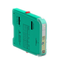
Frequency Converter with Trip Values HiD2891
- 1-channel isolated barrier
- 24 V DC supply (bus powered)
- Dry contact, mag pickup, NAMUR or current/voltage inputs
- Configurable by PACTware or DIP switches
- Current or voltage output
- Sink and source mode output
- Relay contact output
- Line fault detection (LFD)


Please note: All product-related documents, such as certificates, declarations of conformity, etc., which were issued prior to the conversion under the name Pepperl+Fuchs GmbH or Pepperl+Fuchs AG, also apply to Pepperl+Fuchs SE.
Datasheet excerpt: Technical data of HiD2891
| General specifications | ||
|---|---|---|
| Signal type | Digital Input | |
| Supply | ||
| Connection | SL1: 1a(-), 1b(-); 2a(+), 2b(+) | |
| Rated voltage | 20.4 ... 30 V DC | |
| Rated current | typ. 65 mA , max. 80 mA at output 20 mA | |
| Power dissipation | typ. 1.5 W, max. 1.9 W | |
| Input | ||
| Connection | SL2: 5a(+), 5b(-); 1a(+), 1b(-); 3a(+), 3b(-), 7a(+) | |
| Rated values | potential free contact or proximity sensor acc. to EN 60947-5-6 (NAMUR) magnetic pick-up: 100 mVpp ... 20 Vpp, base threshold selectable as 50 mV or 500 mV current logic level: low level < 7 mA, high level > 9 mA voltage logic level: low level < 1.5 V, high level > 3.5 V, max. 28 V |
|
| Connectable sensor types | potential free contact or proximity sensor , magnetic pick-up, voltage or current level | |
| Input resistance | magnetic pick-up: 10 kΩ current logic level: 50 Ω voltage logic level: 30 kΩ |
|
| Input frequency | max. 10 kHz | |
| Pulse duration | min. 40 µs | |
| Output | ||
| Connection | SL1: 10a(+), 9a(-); 8a(+), 7a(-); 8b, 9b, 10b | |
| Output | analog output: proportional to input frequency digital output: optocoupled transistor relay output: SPDT |
|
| Output signal | analog output: - current source 0/4 ... 20mA, load 0 ... 550 Ω - current sink 0/4 ... 20mA, working voltage 3 ... 30 V - voltage 0/1 ... 5 V on internal shunt 250 Ω - voltage 0/2 ... 10 V on internal shunt 500 Ω |
|
| Ripple | typ. 15 mV eff | |
| Contact loading | relay output: 50 V DC , 0.5 A non-inductive digital output: 30 V DC, 50 mA zener protected for inductive load |
|
| Leakage current | digital output typ. 5 µA , max. 50 µA | |
| Saturation voltage | digital output 1.2 V at 50 mA | |
| Fault indication output | ||
| Connection | SL1: 6b | |
| Output type | relay output: high/low alarm, input repeater (max. 5 Hz), error message fault bus signal: open collector transistor on common bus |
|
| Transfer characteristics | ||
| Calibrated accuracy | < ± 0.1 % of full-scale value (current output) | |
| Resolution | < 10 µA | |
| Measuring time | ≥ 100 ms | |
| Influence of temperature | < ± 0.01 %/ K , typ. ± 0.005%/K | |
| Frequency range | 0.001 ... 10000 Hz | |
| Influence of load | < 0.1 % of full-scale value from 0 ... 550 Ω | |
| Response delay | ≤ 200 ms | |
| Galvanic isolation | ||
| Output/power supply | functional insulation acc. to DIN EN 50178, rated insulation voltage 50 Veff | |
| Output/Output | functional insulation acc. to DIN EN 50178, rated insulation voltage 50 Veff | |
| Indicators/settings | ||
| Display elements | LED PWR ON (power supply), one green LED LED STATUS (output status), one yellow LED LED RELAY (relay status), one yellow LED LED FAULT (lead fault), one red LED |
|
| Control elements | DIP switches at the housing side for: input: - selection of input type (potential free contact, proximity sensor, magnetic pick-up, current logic level or voltage logic level) - selection of base threshold by magnetic pick-up (50 mV or 500 mV) output - selection of output type (current sink, current source, voltage) - selection of voltage output range (0 ... 5 V or 0 ... 10 V) |
|
| Factory setting | input type: proximity sensor input range: 0 ... 10 kHz analogue output type: 4 ... 20 mA (NE43) digital output repeater: enable relay output: error monitoring |
|
| Labeling | space for labeling at the front | |
| Directive conformity | ||
| Electromagnetic compatibility | ||
| Directive 2004/108/EC | EN 61326-1:2006 | |
| Conformity | ||
| Galvanic isolation | EN 50178 | |
| Electromagnetic compatibility | NE 21:2006 For further information see system description. |
|
| Degree of protection | IEC 60529 | |
| Input | EN 60947-5-6 | |
| Ambient conditions | ||
| Ambient temperature | -20 ... 60 °C (-4 ... 140 °F) | |
| Relative humidity | 5 ... 90 %, non-condensing up to 35 °C (95 °F) | |
| Mechanical specifications | ||
| Degree of protection | IP20 | |
| Mass | approx. 140 g | |
| Dimensions | 18 x 106 x 128 mm (0.7 x 4.2 x 5 inch) | |
| Height | 106 mm | |
| Width | 18 mm | |
| Length | 128 mm | |
| Mounting | on termination board | |
| Coding | pin 1, 2 and 4 trimmed For further information see system description. |
|
| Data for application in connection with hazardous areas | ||
| EU-type examination certificate | CESI 02 ATEX 086 , for additional certificates see www.pepperl-fuchs.com | |
| Marking |  II (1)G [Ex ia Ga] IIC , II (1)D [Ex ia Da] IIIC II (1)G [Ex ia Ga] IIC , II (1)D [Ex ia Da] IIIC |
|
| Input | Ex ia, Ex iaD | |
| Voltage | 5a(+), 5b(-): 10 V 1a(+), 1b(-): 10 V 3a(+), 3b(-): 1.5 V 7a(+), 3b(-): 1.5 V |
|
| Voltage | 1a(+), 1b(-): 30 V 3a(+), 3b(-): 29 V 7a(+), 3b(-): 30 V |
|
| Current | 5a(+), 5b(-): 10 mA 1a(+), 1b(-): 1 mA 3a(+), 3b(-): 1 mA 7a(+), 3b(-): 1 mA |
|
| Current | 3a(+), 3b(-): 110 mA | |
| Power | 5a(+), 5b(-): 25 mW 1a(+), 1b(-): 2.5 mW 3a(+), 3b(-): 0.4 mW 7a(+), 3b(-): 0.4 mW |
|
| Power | 3a(+), 3b(-): 666 mW | |
| Supply | ||
| Maximum safe voltage | 250 V AC (Attention! Um is no rated voltage.) | |
| Certificate | PF 11 CERT 2109 X , observe statement of conformity | |
| Marking | II 3G Ex nA nC IIC T4 Gc |
|
| Galvanic isolation | ||
| Input/Output | safe electrical isolation acc. to EN 60079-11: 2007, voltage peak value 375 V | |
| Input/power supply | safe electrical isolation acc. to EN 60079-11: 2007, voltage peak value 375 V | |
| Directive conformity | ||
| Directive 94/9/EC | EN 60079-0:2009, EN 60079-11:2007, EN60079-15:2005 , EN 60079-26:2007 , EN 61241-11:2006 | |
| General information | ||
| Supplementary information | EC-Type Examination Certificate, Statement of Conformity, Declaration of Conformity, Attestation of Conformity and instructions have to be observed where applicable. For information see www.pepperl-fuchs.com. | |
Classifications
| System | Classcode |
|---|---|
| ECLASS 13.0 | 27210128 |
| ECLASS 12.0 | 27210128 |
| ECLASS 11.0 | 27210128 |
| ECLASS 10.0.1 | 27210128 |
| ECLASS 9.0 | 27210128 |
| ECLASS 8.0 | 27210190 |
| ECLASS 5.1 | 27210121 |
| ETIM 9.0 | EC002918 |
| ETIM 8.0 | EC002918 |
| ETIM 7.0 | EC002918 |
| ETIM 6.0 | EC002918 |
| ETIM 5.0 | EC002475 |
| UNSPSC 12.1 | 39121007 |
Details: HiD2891
Datasheet: HiD2891
| Datasheet | File Type | File Size |
|---|---|---|
| Datasheet HiD2891 | 383 KB | |
| Datenblatt HiD2891 | 385 KB |
Documents: HiD2891
| Manuals | File Type | File Size |
|---|---|---|
| Manual HiD2891 | 1689 KB | |
| System Manual | 5438 KB | |
| Handbuch HiD2891 | 1772 KB | |
| Systemhandbuch | 5450 KB | |
| Instruction manuals | ||
| Инструкции | 169 KB | |
| Instruction manual / Betriebsanleitung | 320 KB | |
| Návod k poużití | 163 KB | |
| Instruktions manual | 163 KB | |
| Instruction manual | 168 KB | |
| Kasutusjuhend | 159 KB | |
| Käyttöohje | 158 KB | |
| Manuel d'instructions | 165 KB | |
| Betriebsanleitung | 170 KB | |
| Οδηγίες χρήσης | 173 KB | |
| Handleiding | 164 KB | |
| Instruction manual / Betriebsanleitung | 162 KB | |
| Használati útmutató | 164 KB | |
| Manuale di istruzioni | 163 KB | |
| Lietošanas pamācība | 161 KB | |
| Instrukciju vadovas | 162 KB | |
| Instrukcja obsługi | 166 KB | |
| Manual de instruções | 164 KB | |
| Manual de utilizare | 164 KB | |
| Návod na poużitie | 163 KB | |
| Navodila za uporabo | 161 KB | |
| Manual de instrucciones | 164 KB | |
| Manual | 160 KB | |
| Documents | ||
| Installation and configuration guide Device Type Manager (DTM) | 8665 KB | |
| Installations- und Konfigurationsanleitung Device Type Manager (DTM) | 8463 KB |
CAD+CAE: HiD2891
| CAD | File Type | File Size |
|---|---|---|
| CAD 2-D / CAD 2-D | ZIP | 16364 KB |
| EPLAN | ||
| EPLAN macros H-System devices (EMA) / EPLAN-Makros Geräte H-System (EMA) | ZIP | 3536 KB |
Approvals+Certificates: HiD2891
| Certificates | File Type | File Size |
|---|---|---|
| Europe CESI ATEX Category (1) D ATEX Category (1) G | 3887 KB | |
| Europe Pepperl+Fuchs ATEX Category 3 G | 446 KB | |
| TUV Nord IECEx Certificate of Conformity | LINK | --- |
Software: HiD2891
| Device type managers (DTM) | File Type | File Size |
|---|---|---|
| DTM Collection Interface Technology 2 / DTM Collection Interface Technology 2 | ZIP | 32633 KB |
| Software Tools | ||
| PACTware 4.1 SP6 / PACTware 4.1 SP6 | ZIP | 43327 KB |
Associated Products: HiD2891
| Accessories | ||||||
|---|---|---|---|---|---|---|
|
||||||
|
||||||


Choose from various selection criteria like safety integrity level, performance level, device function, and signal type and find the SIL/PL assessed device that you are looking for.


Pepperl+Fuchs SE
Lilienthalstraße 200
68307 Mannheim
Germany
info@de.pepperl-fuchs.com
 +49 621 776-0
Pepperl+Fuchs is a leading developer and manufacturer of electronic sensors and components for the global automation market. Continuous innovation, enduring quality, and steady growth have been the foundation of our success for more than 70 years. Pepperl+Fuchs employs 6,300 people worldwide and has manufacturing facilities in Germany, USA, Singapore, Hungary, Indonesia and Vietnam, most of them ISO 9001 certified.