IO-Link Safety
The Bridge Between Functional Safety and Standard Automation
Developed for the Highest Safety Requirements
What has long been thought of as separate is now growing together: The new IO-Link Safety standard bridges the gap between functional safety and standard automation.
The combination of IO-Link Safety and IO-Link now provides a common, consistent communication basis right down to field level. This eliminates system discontinuities, reduces complexity, and supports the seamless integration of safety-related sensor technology and actuators with standard components in a single architecture. The result is transparent, flexible and future-oriented systems with significantly more efficient engineering and higher availability.
This is made possible by consistent standardization: Developed under the umbrella of PROFIBUS & PROFINET International (PI) in the IO-Link community and defined in the IEC 61131-9 and IEC 61139-2 standards, IO-Link Safety meets the highest safety requirements up to SIL 3 (IEC 61508 / IEC 62061) and PL e, Cat. 4 (EN ISO 13849-1).
Find out more about how IO-Link Safety works and how you too can benefit from this major evolutionary leap.
The Advantages of IO-Link Safety

Future-Ready Investment
A consistent infrastructure for safe and non-safe data that can be scaled as required significantly reduces costs and creates long-term investment security without dependence on proprietary manufacturer standards. Diagnostic options right down to field level ensure increased plant availability.
Unlimited Flexibility
IO-Link Safety makes it possible to adapt systems quickly and easily to new requirements. A wide variety of components (IO-Link Safety devices, IO-Link devices, OSSDs, and standard I/Os) can be flexibly combined, expanded, or replaced, regardless of the fieldbus used.

System Integration
IO-Link Safety transfers proven IO-Link principles to the world of functional safety. Devices can be clearly assigned, parameters of IO-Link Safety and IO-Link devices are saved, and a quick exchange is possible. IODDs and dedicated tools simplify engineering and parameterization, while standardized M12 cabling makes installation much more efficient compared to the parallel wiring that was previously typical for safety.

More than Just Safety
In addition to safe signals, IO-Link Safety provides safe digital measured values (depending on the sensor principle) as well as additional device data and creates transparency up to higher-level systems. Information such as temperature, switching cycles, energy consumption, or other diagnostic data form the basis for well-founded optimization, condition monitoring, and predictive maintenance.
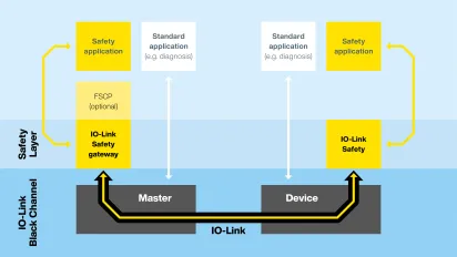
Black Channel Communication: Safe Data via a Common Channel
IO-Link Safety can be integrated into different safety architectures and allows safe and non-safe signals to be transmitted together on one line.
Functional safety in architectures based on IO-Link Safety is ensured by the black channel principle: Here, the actual signal path is not monitored ("black channel"), but possible transmission errors are reliably detected between the IO-Link Safety master and device using mechanisms such as checksums, time monitoring and sequence checks, and unsafe states are avoided. Thanks to this implementation between the IO-Link Safety master and device, IO-Link Safety can be used independently of the Functional Safety Communication Profile (FSCP, e.g. PROFIsafe) used and thus across different fieldbus systems.
As shown in the diagram, safety and standard data are transmitted in parallel while remaining logically separated from each other. As a result, despite the integrative overall concept, safe communication up to SIL 3 and PL e remains clearly defined, while additional data is available for diagnostics and IIoT applications.
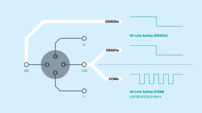
Clear Structure Down to the Connector: The Pin Assignment of IO-Link Safety
IO-Link Safety uses standard IO-Link mechanisms such as the established M12 plug connection and a standardized pinout for the joint transmission of safe and non-safe signals. As shown in the graphic, the supply voltage is applied to pin 1 and pin 3. The C/Q wire on pin 4 is used to transmit the IO-Link Safety communication including the safety data.
As an alternative to operation as an IO-Link Safety device, sensors and actuators with an IO-Link Safety interface—similar to SIO mode in standard IO-Link—can first be configured via the communication interface and then operated like a classic OSSD with conventional safety technology. In this case, safe signal transmission on pin 4 is supplemented by an additional signal path on pin 2. Both paths are used together (OSSD1e and OSSD2e) to ensure robust and fail-safe transmission. This mode is referred to as OSSDe (OSSD equivalent).
For users, this results in a clearly structured interface: standardized M12 cables remain usable, while safe and non-safe data is routed via a common connector. This reduces wiring effort, simplifies installation and service, and ensures consistent and traceable data and power transmission right down to field level.
Safety Is Changing ...
Functional safety is constantly evolving—from classic, often separate solutions to increasingly integrated and flexible architectures. Get an insight into today's common architecture models and find out why IO-Link Safety is superior to all existing approaches.

Basic versions of safe fieldbus modules are primarily used to acquire and transmit safe input and output signals (FDI/FDO). Typically, OSSD-based sensor technology, emergency stop buttons, or simple actuators are connected and transmitted to a safety controller as summarized digital I/O information via safe fieldbuses such as PROFIsafe or CIP Safety. In addition to safe signals, non-safe digital input and output signals (DI/DO) can also be collected via the same modules.
The range of functions is limited to the pure processing of binary input and output signals. Additional diagnostic, measurement, or device data is not available, nor can measured values be transmitted. Parameterization of the connected devices is also not possible and, if necessary, is performed directly on the device.
This architecture enables simple and robust implementation of functional safety, but reaches its limits as soon as secure measured values, further information, or tighter integration are required. The lack of data integration and limited scalability lead to limited transparency, especially in larger systems.
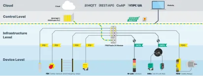
Safe fieldbus modules in an extended version with additional functions, such as those offered by Pepperl+Fuchs with the ICE12/13 series, expand the classic I/O approach with additional data and diagnostic options. In addition to safe input and output signals (FDI, FDO, FDX), further information about connected devices, such as diagnostic or measured values, can also be recorded and transmitted via IO-Link. Although this additional device data is available, it is not part of the safe communication and must therefore not be used for safety-related decisions.
For users, the use of such safe fieldbus modules in an extended version results in improved transparency at device level as well as extended options for diagnostics and servicing. IIoT functions are also supported by integrated interfaces such as MQTT, REST API, or OPC UA. At the same time, the basic architecture remains unchanged: Safety and additional data are managed in parallel, but are not linked to each other.
This solution therefore represents a further development of classic I/O-based safety approaches, but does not yet achieve complete integration of safe communication and device data.

Safety over IO-Link uses existing IO-Link infrastructures to transmit safe and non-safe I/O signals via common cabling.
However, the approach remains limited to the transmission of I/O signals and continues the known limits of classic safety architectures. A consistent integration of communication, safety, and device data is not achieved. In addition, these are manufacturer-specific implementations. Customers are therefore tied to proprietary manufacturer systems and do not benefit from the advantages of a comprehensive standard such as IO-Link Safety offers.
... Towards an All-Encompassing Approach

Unlike other architectures, IO-Link Safety combines safety communication, standard communication, and additional device data on a standardized point-to-point connection.
An IO-Link Safety master provides the interface to higher-level safe fieldbuses such as PROFIsafe and, in the future, CIP Safety or FailSafe over EtherCAT (FSoE), enabling IO-Link Safety devices to be used in different safe fieldbus environments. At the same time, the system offers unprecedented flexibility and openness and supports mixed applications with IO-Link, IO-Link Safety, as well as safe and non-safe signals on one master.
IO-Link Safety is therefore not positioned as a counter-design to the established fieldbus-based safety, but as its consistent extension down to the field level. Users benefit from standardized integration, manufacturer independence, and the ability to use not only safe I/O information but also safe data and additional device data in a structured manner.
Application Example

The example shown uses a palletizing cell to illustrate the benefits of an architecture consisting of IO-Link Safety and IO-Link in practice.
On the upstream roller conveyor, IO-Link retroreflective sensors reliably detect the incoming pallets and at the same time provide additional status information for a stable material flow. The transfer point to the palletizing cell is protected by an IO-Link Safety light grid, which supports targeted single beam evaluation and shutdown. The activation of the beam switch-off is controlled in the safety system based on the identification data of an IO-Link RFID read/write head as well as additional safe conditions such as position and movement sequence. Meanwhile, the rest of the protection field remains active and is continuously monitored. Door locking and emergency stop are also connected via IO-Link Safety, while an IO-Link-based signal beacon clearly visualizes the current system status for the operating personnel.
These links between regular process monitoring and safety functions reduce unnecessary downtimes. At the same time, the integration effort is reduced as all relevant information is processed within a common, IO-Link-based communication structure.
Enabling Change: Interoperable IO-Link and IO-Link Safety Components
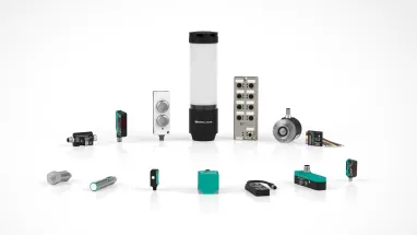
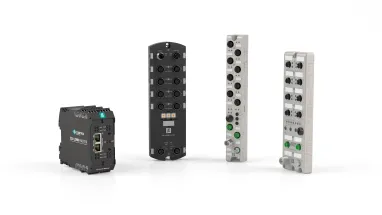
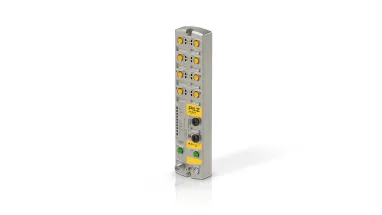
The integration of automation and functional safety requires more than just individual components—a coordinated overall system is crucial. Only the interaction of intelligent IO-Link and IO-Link Safety sensors as well as IO-Link and IO-Link Safety masters enables consistent communication down to field level. This creates consistent data structures, reduced interfaces, and the basis for efficient, future-oriented systems.
Contact Us
Feel free to contact us if you have any further questions about IO-Link Safety or are already planning specific projects. Our experts look forward to hearing from you.