

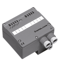
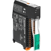
AS-Interface analog module VBA-2A-G4-U
- Degree of protection IP65
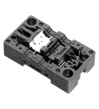
- Flat or round cable connection (via standardized EEMS base, not included with delivery)
- Cable piercing method for flat cable
- Function display for bus, external auxiliary voltage and outputs
- Power supply of outputs external or from the module, as required


Please note: All product-related documents, such as certificates, declarations of conformity, etc., which were issued prior to the conversion under the name Pepperl+Fuchs GmbH or Pepperl+Fuchs AG, also apply to Pepperl+Fuchs SE.
Download the complete datasheet as a PDF:
Datasheet excerpt: Technical data of VBA-2A-G4-U
| Product Description |
|---|
| G4 module IP65 2 analog outputs (voltage) |
| General specifications | ||
|---|---|---|
| Node type | Standard node | |
| AS-Interface specification | V2.1 | |
| Required gateway specification | ≥ V2.1 | |
| UL File Number | E223772 | |
| Functional safety related parameters | ||
| MTTFd | 145 a at 30 °C | |
| Indicators/operating means | ||
| LED FAULT | error display; LED red red: communication error red flashing: peripheral error |
|
| LED PWR | AS-Interface voltage; LED green | |
| LED ANALOG | status output signal; LED green green: 0 V ≤ U ≤ 11.5 V green flashing: U > 11.5 V (peripheral error) |
|
| LED AUX | ext. auxiliary voltage UAUX ; LED green | |
| Electrical specifications | ||
| Auxiliary voltage (output) | 24 V DC ± 15 % PELV | |
| Rated operating voltage | 26.5 ... 31.6 V from AS-Interface | |
| Rated operating current | ≤ 80 mA | |
| Protection class | III | |
| Output | ||
| Number/Type | 2 analog outputs (voltage), 0 ... 10 V | |
| Supply | from AS-Interface or from external auxiliary voltage as required UAUX | |
| Resolution | 13 Bit / 1 mV | |
| Directive conformity | ||
| Electromagnetic compatibility | ||
| Directive 2014/30/EU | EN 62026-2:2013 | |
| Standard conformity | ||
| Degree of protection | EN 60529:2000 | |
| AS-Interface | EN 62026-2:2013 | |
| Programming instructions | ||
| Profile | S-7.3.5 | |
| IO code | 7 | |
| ID code | 3 | |
| ID2 code | 5 | |
| Data bits (function via AS-Interface) | The transfer of the data value is based on AS-Interface Profile 7.3. | |
| Parameter bits (programmable via AS-i) | function | |
| P0 | not used | |
| P1 | projecting of the 2nd channel P1=1, channel 2 is projected P1=0, channel 2 is not projected |
|
| P2 | Message of peripheral error P2=1, peripheral error is reported P2=0, peripheral error is not reported |
|
| P3 | not used | |
| Ambient conditions | ||
| Ambient temperature | 0 ... 70 °C (32 ... 158 °F) | |
| Storage temperature | -25 ... 85 °C (-13 ... 185 °F) | |
| Mechanical specifications | ||
| Degree of protection | IP65 | |
| Connection | cable piercing method or terminal compartment yellow flat cable/black flat cable or standard round cable inputs/outputs: 2 x M16 x 1.5 cable glands and cage tension spring terminals, 1 x M12 x 1.5 cable gland (not used) |
|
| Material | ||
| Housing | PA 6 GF30 | |
| Mass | 350 g | |
| Dimensions | ||
| Height | 71 mm | |
| Width | 90 mm | |
| Length | 102 mm | |
| Mounting | DIN mounting rail | |
Classifications
| System | Classcode |
|---|---|
| ECLASS 13.0 | 27242601 |
| ECLASS 12.0 | 27242601 |
| ECLASS 11.0 | 27242601 |
| ECLASS 10.0.1 | 27242601 |
| ECLASS 9.0 | 27242601 |
| ECLASS 8.0 | 27242601 |
| ECLASS 5.1 | 27242601 |
| ETIM 9.0 | EC001596 |
| ETIM 8.0 | EC001596 |
| ETIM 7.0 | EC001596 |
| ETIM 6.0 | EC001596 |
| ETIM 5.0 | EC001596 |
| UNSPSC 12.1 | 39121535 |
Details: VBA-2A-G4-U
Function
The VBA-2A-G4-U analogue module has two voltage outputs 0 V ... 10 V. The asynchronous transformation of measured values and the data transfer is accomplished in accordance with AS-Interface profile 7.3. The measured-value transmitter can be supplied from the AS-Interface or from the external auxiliary power via the black flat cable, depending on the wiring of the plug-in jumpers. The resolution of the analogue values is 13 bit.
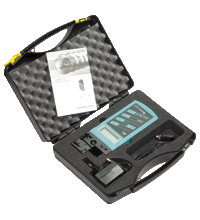
The IP65 rated G4 module is especially suitable for rough conditions. Connection to the outputs is established by means of cable glands and cage tension spring terminals thus making the installation especially user-friendly. For pre-addressing the module it can be plugged directly onto the adapter of the hand-held programming device VBP-HH1.
Both flat and round cables can be used for the connection of the AS-Interface transmission line and the external 24 V DC power supply. Use the U-G1FF base for the AS-Interface flat cable. The AS-Interface standardised EEMS interface, uses the cable piercing method to connect both the yellow and black flat cables.
Use the U-G1PP base for a round cable. The AS-Interface cable as well as the external power supply may be connected within the U-G1PP base.
Product Documentation: VBA-2A-G4-U
| Brief Instructions | Language | File Type | File Size |
|---|---|---|---|
| Mounting Instruction VBA-2A-G4-U / Montageanleitung VBA-2A-G4-U | ALL | 422 KB | |
| Manuals | |||
| Manual VBA-2E-G4-I; VBA-2E-G4-U; VBA-2A-G4-I; VBA-2A-G4-U; VBA-4E-G4-Pt100; VBA-2A-KE2-I/U; VBA-2E-KE2-I/U; VBA-2E-KE2-I/U-V3.0 | ENG | 4051 KB | |
Design / Simulation: VBA-2A-G4-U
| CAD | Language | File Type | File Size |
|---|---|---|---|
| CAD 3-D / CAD 3-D | ALL | STP | 1835 KB |
| CAD Portal / CAD Portal | ALL | LINK | --- |
Approvals: VBA-2A-G4-U
| Certificates | Certificate No. | Language | File Type | File Size |
|---|---|---|---|---|
| Canada, USA UL | CoC 20141115-E223772 | ALL | 342 KB | |
| Declaration of Conformity | ||||
| EU Declaration of Conformity (P+F) / EU-Konformitäterklärung (P+F) | DOC-2448C | ALL | 109 KB | |
Associated Products: VBA-2A-G4-U
| Matching System Components | ||||||
|---|---|---|---|---|---|---|
|
||||||
|
||||||
| Accessories | ||||||
|
||||||
|
||||||


This free PDF white paper compares the different TCP-based communication protocols (AMQP, OPC UA, MQTT, REST API) that have found their way up and are considered the enablers of IIoT and Industry 4.0. Get your free download now!
AS-Interface Switch Cabinet Module KE5 – Simple Handling and Improved Manageability
The unique housing design of the new KE5 switch cabinet module enables distinct visibility and simplifies mounting, wiring, and maintenance inside switch cabinets and junction boxes.


Pepperl+Fuchs (Pty) Ltd
8 Glen Eagle Office Park
Koorsboom Ave, Glen Marais, Kempton Park
1619 Johannesburg
South Africa
info@za.pepperl-fuchs.com
 +27 87985 0797
Pepperl+Fuchs is a leading developer and manufacturer of electronic sensors and components for the global automation market. Continuous innovation, enduring quality, and steady growth have been the foundation of our success for more than 70 years. Pepperl+Fuchs employs 6,300 people worldwide and has manufacturing facilities in Germany, USA, Singapore, Hungary, Indonesia and Vietnam, most of them ISO 9001 certified.