

Connection Methods
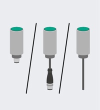
Magnetic field sensors can be electrically integrated into plants in various ways. Various sensor versions with fixed cables with plugs or with connector plugs are available in various designs as standard.
Fixed Cable with Connector
This type of sensor features a fixed cable that can be preassembled. Sensors with fixed cable are affordable versions, since they do not require an additional single-ended female cordset and keep the number of connection points to a minimum.
This type of magnetic field sensor does not have a special marking in the type code.
Electrical Versions and Typical Switching Examples
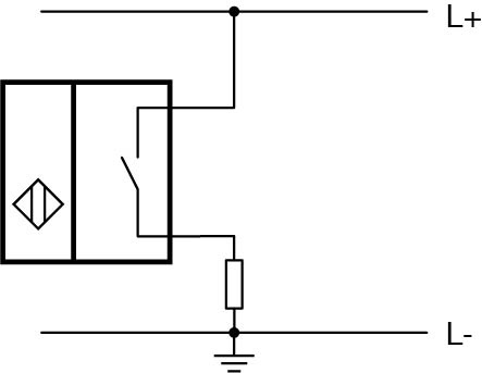
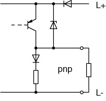
The following table provides an overview of common magnetic field sensors with regard to the electrical design, sensor type, switching examples, and typical data.
| Direct Current Voltage 10 V … 60 V | |
|---|---|
| Sensor type |
|
| Wiring diagram according to EN 60947-5-2 |
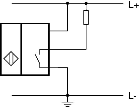
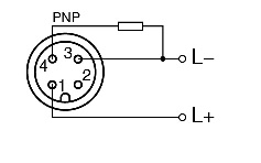
NC contact and NO contact
Example: NO contact Z/Z0 |
| Typical data |
|
Note: This table applies to sensors with electronic output stages. Reed switches are mechanical contacts with magnetic actuation. They have only two connections and are intentionally not listed here.
| Basic Series 10 V … 30 V, 100 mA Standard Series 10 V … 60 V, 200 mA |
|
|---|---|
| Sensor type |
|
| Wiring diagram according to EN 60947-5-2 |
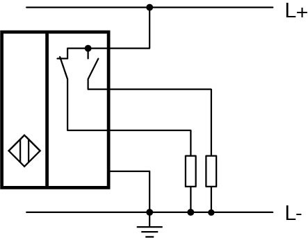
NC contact and NO contact
Example: NO contact E/E0 |
| Basic circuit diagram | 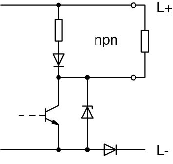 |
 |
|
| Typical data |
|
| Sensor type |
|
| Wiring diagram according to EN 60947-5-2 |
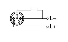
NC contact and NO contact
Example: NC contact and NO contact A2 |
| Typical data |
|
| Direct Current Voltage, 8 V DC | |
|---|---|
| Sensor type |
|
| Wiring diagram according to EN 60947-5-2 |
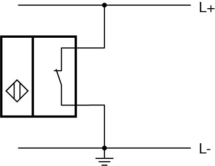
NC contact or NO contact
Example: NC contact N/N0 or SN |
| Typical data |
|
Sensor Types: Core Colors and Pinout According to EN 60947-5-2
The section below provides an overview of the pinout and core colors of the magnetic field sensors.
The pinout numbers correspond to the numbering of the pins on the connector plugs. This does not apply to proximity sensors for AC and those with three-pin 8 mm plugs.
Switches without protective insulation require a protective conductor terminal for voltages above 50 V AC and 120 V DC.
| 3 DC Connections—Observe Polarity | ||
|---|---|---|
| Function | NO contact | |
| Connection/wire colors | + | - | output Brown (BN) | Blue (BU) | Black (BK) |
|
| Pinout | 1 | 3 | 4 | |
| V1 connector plug | 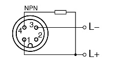 |
 |
| V3 connector plug | 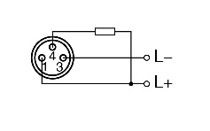 |
 |


Pepperl+Fuchs SE
Lilienthalstraße 200
68307 Mannheim
Germany
info@de.pepperl-fuchs.com
 +49 621 776-0
Pepperl+Fuchs is a leading developer and manufacturer of electronic sensors and components for the global automation market. Continuous innovation, enduring quality, and steady growth have been the foundation of our success for more than 70 years. Pepperl+Fuchs employs 6,300 people worldwide and has manufacturing facilities in Germany, USA, Singapore, Hungary, Indonesia and Vietnam, most of them ISO 9001 certified.