

Available Types of Output
The following section covers the types of output for which magnetic field sensors are available and how these outputs work.
Note: For information on the electrical connection of different sensor versions according to type of output, see Connecting Magnetic Field Sensors.
Magnetic field sensors from Pepperl+Fuchs are switching sensors, i.e., simple on/off switches. They can switch between two defined states and therefore control actuators such as valves, flaps, signal lights, etc.
Magnetic field sensors can be connected to digital inputs of programmable logic controllers.
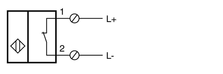
1. Sensor with Reed Switch
The contact switch consists of two ferromagnetic, partially overlapping switch tongues coated with hard metal. The switch tongues are switched via a permanent magnet and the contact is established. A power supply to the sensor is not required or intended (passive sensor). Sensors with a Reed switch are unipolar, i.e., there is no preferred direction of current flow.

Example of a sensor with a Reed contact
2. Sensor with NPN Output (Signal "Negative")
An NPN output of the sensor connects the output connection to ground when switched. The load is connected between the supply voltage L+ and the NPN output of the sensor.
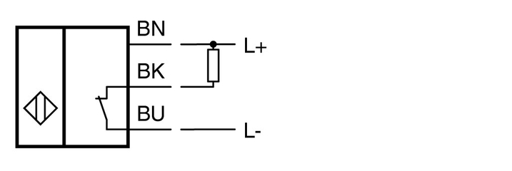
Example of a sensor with NPN output
3. Sensor with PNP Output (Signal "Positive")
A PNP output of the sensor connects the output connection to the supply voltage of the sensor when switched. The load is connected between the PNP output of the sensor and ground L- .
Note: Sensors with PNP output tend to be used more frequently to prevent short circuits to ground.
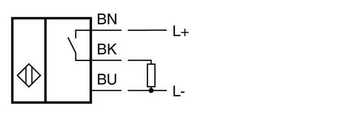
Example of a sensor with PNP output
4. Sensor with Two-Wire Function
Magnetic field sensors with two-wire function use this common type of output with only two output cables for power supply and signal transmission.
The sensor is operated in series to the connected load. In a series connection, the order in which the sensor and load are arranged is irrelevant.
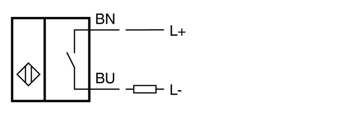
Example of a sensor with two-wire function
How It Works
A sensor with two-wire function is an active component that requires energy to function. The sensor is supplied with this electrical energy via the two connecting wires. At the same time, the sensor signals its switch state via the same connecting wires.
A sensor with two-wire function is often equated with a mechanical switch in terms of how it works. Nevertheless, this type of sensor works differently than a mechanical switch, which is open or closed depending on the sensor's damping situation. No current flows through an open mechanical switch. The connected load is not energized. Conversely, in an ideal situation, voltage does not drop via a closed mechanical switch. The entire supply voltage is applied across the load.
In contrast, a sensor with two-wire function—as an active component—requires voltage and current at all times. Even in the closed state, a non-negligible voltage, missing from the connected load, drops across the sensor. When open, a current flows through the sensor and the connected load. Therefore, when operating a sensor with two-wire function, the unique states "open" and "closed" never exist.
Sensors with two-wire function are often operated at digital inputs of a programmable logic controller (PLC). Depending on their type, these digital inputs have an input impedance according to EN 61131-2. This must be considered when selecting the sensor with two-wire function.
Occasionally, sensors with two-wire function are operated on discrete loads. The individual resistance value of the load must be taken into account. The technical data for sensors with two-wire function does not provide any specific information on this since the resistance value depends on the operating voltage of the plant and the minimum and maximum operating current of the sensor.
5. Sensor with NAMUR Output Signal
A sensor of this type of output generates output signals that correspond to the NAMUR specifications.
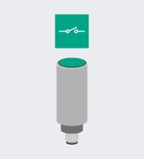
Example of a sensor with a NAMUR output signal
How It Works
NAMUR sensors are 2-wire sensors that represent the switch state via specific current values as defined in the EN 60947-5-6 standard. NAMUR sensors are usually connected to isolated switch amplifiers that interpret the current values of the NAMUR sensor and convert them into discrete switching outputs. Together with a suitable isolated switch amplifier, NAMUR sensors form an intrinsically safe circuit for use in explosion-hazardous areas. Alongside the switching output control, the isolated switch amplifier provides short-circuit and lead-breakage detection.
Versions:
Traditionally, NAMUR sensors have a constant output characteristic. NAMUR sensors with this output characteristic are marked with an "N" in the type code.
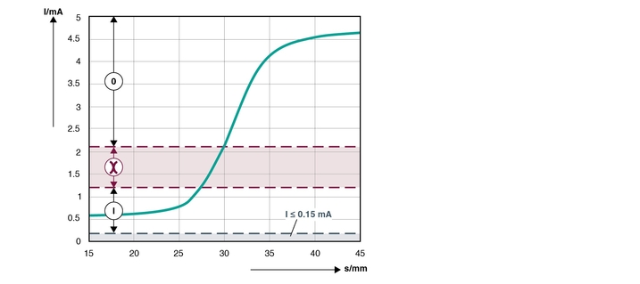
Area 0: unactuated area
Red area between 0/I: impermissible area of the switch amplifier
Area I: actuated range
Area ≤ 0.15 mA: lead breakage
Area ≥ 6.5 mA: short circuit
In addition, Pepperl+Fuchs offers NAMUR sensors with binary switching characteristics. NAMUR sensors with this output characteristic are marked with "N0" (normally-closed characteristics) or "N1" (normally-open characteristics) in the type code.
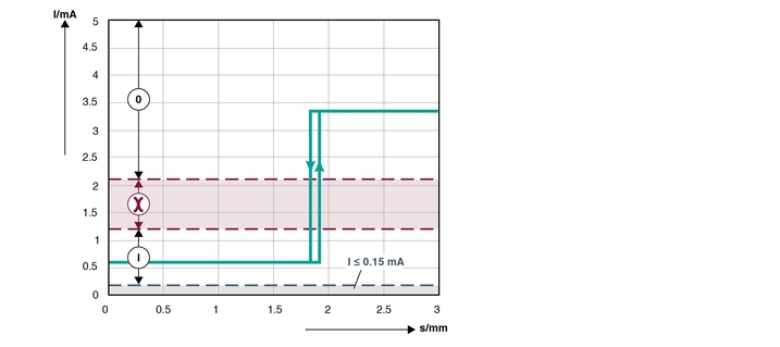
Area 0: unactuated area
Red area between 0/I: impermissible area of the switch amplifier
Area I: actuated range
Area ≤ 0.15 mA: lead breakage
Area ≥ 6.5 mA: short circuit
Output Logic
A typical switching element function of magnetic field sensors is binary "switching." Based on two different states, different functions are possible. The repeat accuracy and switching hysteresis must be observed.


Pepperl+Fuchs SE
Lilienthalstraße 200
68307 Mannheim
Germany
info@de.pepperl-fuchs.com
 +49 621 776-0
Pepperl+Fuchs is a leading developer and manufacturer of electronic sensors and components for the global automation market. Continuous innovation, enduring quality, and steady growth have been the foundation of our success for more than 70 years. Pepperl+Fuchs employs 6,300 people worldwide and has manufacturing facilities in Germany, USA, Singapore, Hungary, Indonesia and Vietnam, most of them ISO 9001 certified.