

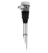
Conductive Level Limit Switch LKL-P*
- Level limit switch for conductive liquids
- Detect up to five level limits with one probe
- Flexible instrumentation
- No moving parts in the tank
- No calibration: quick and low-cost start up
- Option between rod or rope version for optimum adaptation to the application
- Two-point control and additional maximum and minimum detection
- Approval as overfill protection and leak detection system acc. to WHG


Please note: All product-related documents, such as certificates, declarations of conformity, etc., which were issued prior to the conversion under the name Pepperl+Fuchs GmbH or Pepperl+Fuchs AG, also apply to Pepperl+Fuchs SE.
Descargue la hoja de datos completa en PDF:
Extracto de la hoja de datos: Información técnica del LKL-P*
| Directive conformity | ||
|---|---|---|
| Electromagnetic compatibility | ||
| Directive 2014/30/EU | EN 61326-1:2006 , EN 61326-2-3:2006 | |
| Low voltage | ||
| Directive 2014/35/EU | EN 61010-1:2001 | |
| Conformity | ||
| Electromagnetic compatibility | NE 21 | |
| Degree of protection | IEC 60529:2001 | |
| Vibration resistance | EN 60068-2-64 | |
| Climate class | EN 60068, part 2-38 (test Z/AD) | |
| Function and system design | ||
| Measuring principle | An alternating voltage exists between the probes in an empty tank. As soon as the conductive liquid in the tank creates a connection between the ground probe and, for example, the maximum probe, a measurable current flows and the device switches. With level limit detection, the device switches back as soon as the liquid clears the maximum probe. With two-point control, the device does not switch back until the max and min probe is cleared. Using alternating voltage prevents corrosion of the probes and electrolytic destruction of the product. The material used for the tank walls is not important for measurement because the system is designed as a closed potential-free circuit between the probes and the electronics. There is absolutely no danger if the probes are touched during operation. |
|
| Equipment architecture | probe with integrated electronic insert (compact instrument version) probe without integrated electronic insert (separate instrument version) for one, two or multiple point detection respectively, see section measuring system |
|
| Input characteristics | ||
| Measured variable | resistance change between two conductors caused by the presence or absence of a conductive product. | |
| Measurement range | The measuring range is dependent on the mounting location of the probes. Rod probes can have a max. length of 4000 mm (13 ft) and rope probes up to 15000 mm (49 ft). |
|
| Input signal | probes covered - A measurable current is flowing between the probes. probes uncovered - There is no measurable current flowing between the probes. |
|
| Output characteristics | ||
| Output signal | see section electrical connection | |
| Measurement range | A total of four measuring ranges (100 Ω, 1 kΩ, 10 kΩ, 100 kΩ) can be set via two DIL switches (SENS). The setting on delivery is 100 kΩ. | |
| Signal on alarm | Output E5 (FEW52): in the event of a power failure or a damaged probe: < 100 µA. output WA (FEW54): output signal in the event of a power failure or a damaged probe: relay de-energised. |
|
| Fail-safe mode | Selecting the correct fail-safe mode ensures that the relay/the output always runs in quiescent current fail-safe. output E5 (FEW52): - maximum fail-safe: The output signal is < 1 mA if the switch point is exceeded (probe covered), a fault occurs or the power supply fails. - minimum fail-safe: The output signal is < 1 mA if the switch point is undershot (probe uncovered), a fault occurs or the power supply fails. Output WA (FEW54): - maximum fail-safe: The relay de-energises when the switch point is exceeded (probe covered), a fault occurs or the power supply fails. - minimum fail-safe: The relay de-energizes when the switch point is undershot (probe uncovered), a fault occurs or the power supply fails. output N1 (FEW58): - maximum fail-safe: The output voltage is 0 V if the switch point is exceeded (probe covered), a fault occurs or the power supply fails. - minimum fail-safe: The output voltage is 0 V if the switch point is undershot (probe uncovered), a fault occurs or the power supply fails. |
|
| Load | Output E5 (FEW52): The load is switched via a transistor (PNP), cycled overload and short-circuit protection, continuous ≤ 200 mA (short-circuit proof), residual voltage at transistor at Imax 2.9 V Output WA (FEW54): Loads are switched via 2 potential-free change-over contacts. I~ max. 4 A, U~ max. 253 V P~ max. 1000 VA, cos φ = 1, P~ max. 700 VA, cos φ > 0.7 I- max. 4 A to 30 V, I- max. 0.2 A to 150 V When connecting a functional extra-low voltage circuit with double insulation in accordance with IEC 1010: The sum of the relay output and power supply voltages is max. 300 V. output N1 (FEW58): refer to datasheet of the connected switch amplifier acc. to IEC 60947-5-6 (NAMUR) |
|
| Switching delay | A switching delay of 2.0 s can be activated or deactivated via a DIL switch. If the switching delay is set to 0 s, the device switches after approx. 0.3 s. |
|
| Galvanic isolation | output WA (FEW54): All input channels, output channels and relay contacts are galvanically isolated from each other. | |
| Lead monitoring | For probes without an electronic insert, an additional printed circuit board must be installed in the housing, which enables cable monitoring. It is always switched or connected between rod/rope 1 and 2. Note! When using switching units (transmitters) that do not support cable monitoring, these must be removed. |
|
| Auxiliary energy | ||
| Electrical connection | see section electrical connection | |
| Supply voltage | Output E5 (FEW52): supply voltage 10.8 ... 45 V DC load connection: open collector; PNP switching voltage: max. 45 V Output WA (FEW54): supply voltage 20 ... 55 V DC or 20 ... 253 V AC, 50/60 Hz peak inrush current: max. 2 A, max. 400 µs output: two potential-free change-over contacts output N1 (FEW58): refer to datasheet of the connected switch amplifier acc. to IEC 60947-5-6 (NAMUR) |
|
| Power consumption | Output E5 (FEW52): P < 1.1 W output WA (FEW54): P < 2.0 W |
|
| Current consumption | Output E5 (FEW52): I < 25 mA (without load) output WA (FEW54): 60 mA |
|
| Reverse polarity protection | output E5 (FEW52) | |
| Contact loading | output WA (FEW54): 253 V AC/4 A, 30 V DC/4 A, 150 V/ 0.2 A | |
| Signal on alarm | output N1 (FEW58): output signal with damaged sensor < 1 mA | |
| Measurement accuracy | ||
| Reference operating conditions | ambient temperature: 23 °C (296 K), medium temperature: 23 °C (296 K), medium viscosity: medium must release the probe again (drain off), medium pressure pe: 0 bar, probe installation: vertically from above |
|
| Maximum measured error | ± 10 % at 0.1 ... 100 kΩ ± 5 % at 1 ... 10 kΩ |
|
| Non-repeatability | ± 5 % at 0.1 ... 100 kΩ ± 1 % at 1 ... 10 kΩ |
|
| Hysteresis | -10 % for the max probe, in reference to the switch point, Δs function deactivated | |
| Influence of ambient temperature | < 0.05 %/K | |
| Switching time | < 3 s | |
| Operating conditions | ||
| Installation conditions | ||
| Mounting location | The rod and rope probes are mounted predominantly in tanks made of plastic or metal. | |
| Mounting examples | see section example applications | |
| Ambient conditions | ||
| Ambient temperature | -40 ... 70 °C (-40 ... 158 °F) -40 ... 60 °C (233 ... 333 K) for output N1 (FEW58) |
|
| Storage temperature | -40 ... 80 °C (-40 ... 176 °F) | |
| Climate class | tropicalized | |
| Shock resistance | practical test | |
| Vibration resistance | 20 ... 2000 Hz, 1 (m/s2)2/Hz | |
| Process conditions | ||
| Medium temperature | -40 ... 100 °C (-40 ... 212 °F) | |
| Medium pressure | -1 ... 10 bar (-14.5 ... 145 psi) | |
| Conductivity | ≥ 10 µS | |
| Mechanical specifications | ||
| Degree of protection | IP66 | |
| Data for application in connection with hazardous areas | ||
| EU-type examination certificate | TÜV 03 ATEX 2295 | |
| Marking |  II 2G Ex ia/ib IIC T4 II 2G Ex ia/ib IIC T4 |
|
| Directive conformity | ||
| Directive 2014/34/EU | EN 60079-0:2009 , EN 60079-11:2007 | |
| Mechanical construction | ||
| Construction type | LKL-P1: rod version LKL-P2: rope version |
|
| Dimensions | LKL-P1: - housing: max. Ø85 mm (3.3 inch), height max. 145 mm (5.7 inch) - rod: length 100 ... 4000 mm (4 in ... 13 ft) LKL-P2: - housing: max. Ø85 mm (3.3 inch), height max. 145 mm (5.7 inch) - rope: length 250 ... 15000 mm (10 in ... 49 ft) |
|
| Mass | separate instrument version: - rod, 1 m (3 ft) long, LKL-P1 with 2, 3 or 5 rods: 415 g, 530 g, 760 g - rope, 1 m (3 ft) long, LKL-P2 with 2, 3 or 5 ropes: 390 g, 470 g, 640 g compact instrument version: - rod, 1 m (3 ft) long, LKL-P1 with 2 or 3 rods (600 g/720 g) - rope, 1 m (3 ft) long, LKL-P2 with 2 or 3 ropes (710 g/800 g) |
|
| Material | probes: - rods: rod 1.4404/316L, insulation: PP - ropes: rope 1.4571/316Ti, insulation FEP, weight 1.4435/316L housing: - output NA (separate instrument version): housing PPS, cover PBT - output E5/WA/N1 (compact instrument version): housing PBT, cover PBT, adapter PBT process connections: PPS |
|
| Process connection | - cylindrical thread G1½A to DIN ISO 228/1 - conical thread 1½ NPT to ANSI B 1.20.1 |
|
| Probe | rod probes: compact instrument version 2 or 3 rods, separate instrument version 2, 3 or 5 rods - diameter without insulation: Ø4 mm (0.16 inch) - rod length: 100 ... 4000 mm (4 in ... 13 ft) - thickness of insulation: 0.5 mm (0.02 inch) - length of non-insulated area (tip of rod): 20 mm (0.8 inch) - extraction forces: 1000 N rope probes: compact instrument version 2 or 3 ropes, separate instrument version 2, 3 or 5 ropes - diameter without insulation: Ø1 mm (0.04 inch) - rope length: 250 ... 15000 mm (10 inch ... 49 ft) - thickness of insulation: 0.75 mm (0.03 inch) - weight length: 100 mm (4 inch) (not insulated) - weight diameter: Ø10 mm (0.4 inch) - extraction forces: 500 N |
|
| Electrical connection | cable connection M20x1.5, 1/2NPT, G1/2 | |
| Indication and operation | ||
| Display elements | separate instrument version: dependent on the connected switching unit compact instrument version: output E5 (FEW52), WA (FEW54): - one red light emitting diode: fault message, switching status - one green light emitting diode: operation output N1 (FEW58): - one yellow light emitting diode: fault message, switching status - one green light emitting diode: operation |
|
| Control elements | - one DIL switch for min/max position - one DIL switch for 0 s or 2 s switching delay - two DIL switches for setting the measuring ranges 100 Ω, 1 kΩ, 10 kΩ, 100 kΩ |
|
| Certificates and approvals | ||
| Overspill protection | see approval (ZE) | |
| General information | ||
| Supplementary documentation | technical information TI375O operating instructions KA203O (LKL-P* without electronic insert) operating instructions KA204O (LKL-P* with integrated electronic insert) safety information SI230O (TÜV 03 ATEX 2295) safety information SI226O ( II 3G EEx nA [L] IIC T6 or nC [L])approval ZE043O overspill protection acc. to WHG (Z-65.13-378) approval ZE257O leak detection system (Z-65.40-379) |
|
| Supplementary information | EC-Type Examination Certificate, Statement of Conformity, Declaration of Conformity, Attestation of Conformity and instructions have to be observed where applicable. For information see www.pepperl-fuchs.com. | |
Classifications
| System | Classcode |
|---|---|
| ECLASS 13.0 | 27200507 |
| ECLASS 12.0 | 27200507 |
| ECLASS 11.0 | 27200507 |
| ECLASS 10.0.1 | 27200507 |
| ECLASS 9.0 | 27200507 |
| ECLASS 8.0 | 27200507 |
| ECLASS 5.1 | 27200507 |
| ETIM 9.0 | EC001447 |
| ETIM 8.0 | EC001447 |
| ETIM 7.0 | EC001447 |
| ETIM 6.0 | EC001447 |
| ETIM 5.0 | EC001447 |
| UNSPSC 12.1 | 41111950 |
Details: LKL-P*
Product Documentation: LKL-P*
| Product information | Idioma | Tipo de archivo | Tamaño |
|---|---|---|---|
| TI375O, Technical information LKL-P* | ENG | 1265 KB | |
| Brief Instructions | |||
| KA203O, brief instructions LKL-P* without electronic insert / KA203O, Kurzanleitung LKL-P* ohne Elektronikeinsatz | ALL | 464 KB | |
| KA204O, brief instructions LKL-P* with electronic insert / KA204O, Kurzanleitung LKL-P* mit Elektronikeinsatz | ALL | 623 KB | |
| Safety and Security Documentation | |||
| SI226O-A, Instruction manual LKL-P* / SI226O-A, Betriebsanleitung LKL-P* | ALL | 237 KB | |
| SI230O-A, Instruction manual LKL-P* / SI230O-A, Betriebsanleitung LKL-P* | ALL | 692 KB | |
Approvals: LKL-P*
| Certificates | Número de Certificado | Idioma | Tipo de archivo | Tamaño |
|---|---|---|---|---|
| Europe DIBT WHG Leak Detection | Z-65.40-379 | ALL | 533 KB | |
| Europe DIBT WHG Overspill Protection | Z-65.13-378 | ALL | 533 KB | |
| Europe TUV Nord ATEX Category 2 G | TÜV 03 ATEX 2295 | ALL | 350 KB | |
| Declaration of Conformity | ||||
| Declaration of Conformity for simple apparatus / Konformitätserklärung für einfache Betriebsmittel | DOC-1837E | ALL | 390 KB | |
| EU Declaration of Conformity (P+F) / EU-Konformitäterklärung (P+F) | DOC-2087D | ALL | 351 KB | |
| EU Declaration of Conformity (P+F) / EU-Konformitäterklärung (P+F) | DOC-2086D | ALL | 344 KB | |
| Contamination Declaration | ||||
| Contamination declaration / Kontaminationserklärung | ALL | 137 KB | ||


Pepperl+Fuchs SE
Lilienthalstraße 200
68307 Mannheim
Germany
info@de.pepperl-fuchs.com
 +49 621 776-0
Pepperl + Fuchs es líder en el desarrollo y la fabricación de sensores electrónicos y componentes para el mercado de la automatización global. Su incesante innovación, calidad duradera y crecimiento constante garantizan el éxito continuado, desde hace más de 70 años. Pepperl + Fuchs emplea a 6.300 personas en todo el mundo y cuenta con fábricas en Alemania, EE.UU., Singapur, Hungría, Indonesia y Vietnam, la mayoría de ellas con certificado ISO 9001.